Overview
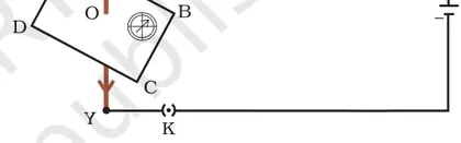
This chapter introduces the magnetic effects of electric current — how a current produces a magnetic field and how a magnetic field acts on a current. Starting from Oersted's discovery, students learn the concept of magnetic field and field lines, rules to find field direction (right-hand thumb rule), and patterns produced by straight conductors, circular loops and solenoids. The chapter explains the force on a current-carrying conductor placed in a magnetic field (Fleming's left‑hand rule), the dependence of the force on current, field strength and length (F = BIl), interaction between parallel currents and the operational principles of practical devices such as the electric motor, electromagnet and moving‑coil galvanometer (and its conversion to ammeter and voltmeter). Importance: this chapter links fundamental electromagnetic ideas to real-life applications (motors, meters, relays, loudspeakers) and provides essential foundations for later study of electromagnetism and electrical devices.
Learning Objectives
- Define magnetic field and magnetic field lines and state their properties.
- Explain Oersted's experiment and its significance in demonstrating magnetic effects of electric current.
- Apply the right-hand thumb (or Ampere's) rule to determine the direction of the magnetic field around a straight current-carrying conductor, a circular loop, and a solenoid.
- Sketch and illustrate magnetic field patterns for a straight conductor, a circular current loop, and a solenoid; compare relative field strengths.
- Explain why a solenoid behaves like a bar magnet and describe the magnetic field inside and at the ends of a solenoid.
- Define electromagnet and explain the factors (current, number of turns, core material) that affect its strength.
- Apply Fleming's left-hand rule to determine the direction of force on a current-carrying conductor placed in a magnetic field and predict its motion.
- Use the relation F = BIL to calculate the magnitude of force on a conductor of length L carrying current I in a magnetic field of flux density B for simple numerical problems.
Topics in this chapter
12 topics · tap a topic title to jump straight to it.
Introduction and Oersted's Experiment
Introduction
A magnetic effect of electric current means that an electric current produces a magnetic field in the space around the conductor carrying the current. This is the basis of many devices (motors, electromagnets, speakers).
Oersted's Experiment (setup and procedure)
- Place a small magnetic compass on a table and note that its needle points towards the Earth's magnetic north when no current flows.
- Place a straight, horizontal conducting wire just above the compass needle and connect the wire to a battery through a switch.
- Close the switch so that current flows through the wire. Observe the compass needle.
Observations
- When current flows, the compass needle gets deflected from its original direction. The deflection disappears when the current is switched off.
- If the direction of current in the wire is reversed, the needle deflects in the opposite direction.
- The amount of deflection increases with larger current and decreases if the wire is moved farther from the compass.
Conclusions
- A current-carrying conductor produces a magnetic field around it.
- The magnetic field lines around a long straight conductor are concentric circles centred on the wire.
- The direction of the magnetic field around a straight wire is given by the right-hand thumb rule: if the thumb of the right hand points along the direction of conventional current, the curled fingers show the direction of the magnetic field lines.
Qualitative relations
- Magnetic field strength around a straight conductor increases with the current flowing through it.
- Magnetic field strength decreases with distance from the conductor.
Practical notes
Oersted's discovery linked electricity and magnetism and led to development of electromagnets, electric motors and generators. Simple classroom demonstrations use a compass, a straight wire and a battery to show the effect clearly.
- Electric bell: a current through a coil produces a magnetic field that attracts a soft iron armature to strike the bell.
- Electric motor: current in coil segments produces magnetic fields that interact with permanent magnets to create rotation.
- Loudspeaker: varying current through a coil produces changing magnetic fields that move a diaphragm to produce sound.
- Compass deflection near high-current power lines or a subway: people sometimes notice compass deviations close to heavy current-carrying conductors.
- Electromagnetic crane: large current in coils creates a strong magnetic field that lifts scrap metal when energized.
- Qualitative proportionalities: B ∝ I (magnetic field strength ∝ current), B ∝ 1/r (field strength decreases with distance r from a long straight conductor).
- Exact expression for a long straight conductor (in free space): B = μ0 * I / (2π * r), where μ0 = 4π × 10^(-7) T·m/A, I = current (A), r = perpendicular distance from the wire (m).
- Right-hand thumb rule (direction rule): not a numerical formula but a rule to find field direction—point thumb in current direction, curled fingers give field direction (circular around wire).
Magnetic Field and Magnetic Field Lines
Magnetic field (B) is the region around a magnet, a current-carrying conductor or a changing electric field in which magnetic forces can be detected. At any point the magnetic field has a direction and magnitude. The SI unit of magnetic field (magnetic flux density) is tesla (T).
Magnetic field lines are imaginary continuous curves used to represent the magnetic field. They show both the direction and relative strength of the field. Important features:
- Field line direction: tangent to a field line at any point gives the direction of the magnetic field at that point.
- Line sense: outside a magnet, lines go from the north (N) pole to the south (S) pole; inside the magnet they return from S to N, so lines are closed loops.
- Density: where lines are closer the field is stronger; where they are sparse the field is weaker.
- Never cross: two field lines do not intersect. If they did, the field would have two directions at one point, which is impossible.
Field due to a straight current-carrying conductor:
- Magnetic field lines around a long straight current are concentric circles centered on the wire.
- Direction rule: use the right hand thumb rule (thumb along current, fingers curl in the direction of field lines).
- Magnitude for a long straight wire at a distance r from the wire:
B = (μ0 I) / (2π r)
where μ0 = 4π × 10−7 T·m/A, I is current, r is radial distance. This shows B ∝ I and B ∝ 1/r.
Field due to a circular current loop:
- Field lines pass through the center and form closed loops; at the center of a single circular loop of radius R carrying current I:
B = (μ0 I) / (2R)
Field due to a solenoid (tightly wound coil):
- Inside a long solenoid the field is approximately uniform and parallel to the axis; outside it is weak and spreads out.
- For an ideal long solenoid with n turns per unit length (n = N/L):
B = μ0 n I
Direction given by the right hand grip rule: curl fingers in the direction of current in the coils; the thumb points toward the north pole (axis direction) of the solenoid.
Practical notes and observations:
- Small magnetic compasses indicate field direction and are used to map field lines experimentally.
- Magnetic field lines show similarity between permanent magnets and fields produced by currents (Ampère-Maxwell relationship).
- In many devices (motors, loudspeakers, relays) interaction between magnetic fields and currents produces motion or force.
- Compass navigation: a compass needle aligns tangent to Earth's magnetic field lines showing field direction.
- Electric bell/solenoid in doorbells: a current through coil produces a magnetic field that attracts the striker.
- Galvanometer and ammeter: uses the torque on a coil in a magnetic field to detect current (field–current interaction).
- Electromagnets in scrapyards: a current in a coil produces a strong magnetic field that lifts heavy ferrous objects.
- Loudspeakers: a current in the voice-coil interacts with a permanent magnet's field to produce sound by moving the cone.
- MRI machines: strong, controlled magnetic fields (and gradients) align nuclear spins for medical imaging (application of uniform solenoid-like fields).
- Magnetic field near a long straight wire: B = μ0 I / (2π r), where μ0 = 4π × 10^−7 T·m/A, I is current (A), r is distance (m).
- Magnetic field at the center of a single circular loop: B = μ0 I / (2R), where R is loop radius (m).
- Magnetic field inside a long solenoid: B = μ0 n I, where n = N/L is turns per unit length (turns/m).
- Qualitative relations: B ∝ I (field strength increases linearly with current), B ∝ 1/r for a long straight wire (field decreases with distance).
Magnetic Field due to a Current in a Straight Conductor
Introduction
When an electric current flows through a straight conductor (wire), it produces a magnetic field in the space around the conductor. This was first observed by Oersted: a compass needle gets deflected when placed near a current-carrying wire, showing that electric currents produce magnetic effects.
Shape and Direction of the Field
The magnetic field lines around a long straight conductor are concentric circles centered on the wire. The direction of the field is given by the right-hand thumb rule: if you hold the wire with your right hand so that the thumb points in the direction of conventional current (from + to −), then the curled fingers show the direction of the magnetic field lines around the wire.
Magnitude of the Field (using Ampere's law)
For a long straight conductor carrying a steady current I, at a distance r from the wire (in air or vacuum), the magnetic field magnitude B is given by Ampere's circuital law. Taking a circular Amperian loop of radius r around the wire:
∮ B·dl = μ0 I_enclosed
Because B is constant on the circular path and tangent to it, B(2πr) = μ0 I, so
B = μ0 I / (2π r)
Here μ0 is the permeability of free space: μ0 = 4π × 10−7 T·m/A. This formula assumes a sufficiently long (ideally infinite) straight wire and steady current. The field decreases inversely with distance (B ∝ 1/r) and increases linearly with current (B ∝ I).
Units and typical values
Magnetic field B is measured in tesla (T). In common situations around household wires the field is very small (microtesla to millitesla), but near high-current transmission lines the fields can be larger.
Experimental evidence
Common experiments: placing a compass near a straight wire shows the needle tangential to concentric circles; placing iron filings on a sheet above the wire shows circular patterns when current flows; moving the compass closer increases deflection (stronger field), and reversing current reverses the direction of deflection.
Assumptions & limitations
The B = μ0 I/(2πr) formula is for a long straight conductor in a homogeneous medium (air/vacuum). For short wires, nearby magnetic materials, or inside conductors, the field distribution differs.
Summary
A straight current-carrying conductor produces circular magnetic field lines around it. Direction is given by the right-hand thumb rule and magnitude by B = μ0 I/(2π r), falling off as 1/r with distance from the wire.
- A straight overhead power transmission line carrying large current produces a magnetic field around it; the field strength at ground depends on current and distance from the line.
- Deflection of a compass needle when brought near a laboratory wire connected to a battery — shows direction and presence of circular magnetic field.
- Iron filings placed on a cardboard over a straight current-carrying wire align into concentric circular patterns around the wire.
- Current sensors (e.g., clamp meters) detect magnetic field around a conductor to measure the current without direct electrical contact.
- B = μ0 I / (2π r) (magnetic field at distance r from a long straight conductor in free space)
- μ0 = 4π × 10^−7 T·m/A (permeability of free space)
- B ∝ I (field is directly proportional to current)
- B ∝ 1/r (field decreases inversely with distance)
- Ampere's law (integral form): ∮ B·dl = μ0 I_enclosed
Magnetic Field due to a Current in a Circular Loop
What is it? A circular loop carrying a steady current I produces a magnetic field in the space around it. The pattern of field lines is similar to that of a bar magnet: lines emerge from one face of the loop, pass through the centre, and return around the outside.
Field shape and direction
- Near the wire of the loop the magnetic field is concentric and circular around each small element of the wire (as given by the right-hand rule for a straight conductor).
- Overall, through the axis of the loop (the line perpendicular to the plane of the loop through its centre) the field is strongest at the centre and decreases as we move away along the axis.
- Direction (Right-hand rule for a loop): Curl the fingers of your right hand in the direction of current flow around the loop. Your thumb points in the direction of the magnetic field on the axis (the 'north' direction of the loop).
Key influences on the field
- Field strength at the centre increases linearly with current I.
- Field strength at the centre decreases with increasing loop radius R (for the same current).
- For N closely wound turns (a coil), the fields from each turn add, increasing the net field approximately by a factor of N.
How the formula is obtained (brief)
The quantitative expression for the magnetic field is obtained using the Biot–Savart law (integration over the circular current). For class 10 purposes you need the result and understanding of dependence on I, R and N rather than the full calculus derivation.
Important special cases
- At the centre of a single circular loop of radius R: B = μ0 I / (2R) directed along the axis.
- At the centre of a coil of N closely wound turns: B = μ0 N I / (2R).
- At a point on the axis a distance x from the centre: B = (μ0 I R^2) / (2 (R^2 + x^2)^(3/2)). This reduces to the centre result when x = 0.
Summary — A current in a circular loop produces a magnetic field like that of a small bar magnet: strongest at the centre, direction given by the right-hand rule, proportional to current and number of turns and inversely related to loop radius.
- Loudspeaker voice coil: A coil (many circular turns) carrying alternating current produces changing magnetic fields that interact with a permanent magnet to move the speaker cone and create sound.
- Electric motors and galvanometers: Circular coils in these devices produce magnetic fields that interact with other magnetic fields to cause rotation or deflection.
- Electromagnets and solenoids: A stack of circular turns (coil) produces a strong field along the axis; used in relays, magnetic cranes and MRI (medical imaging) where strong, controlled magnetic fields are needed.
- Magnetic stirrers: Rotating magnetic fields produced by coils move a magnetic bar in a liquid.
- Magnetic constant: μ0 = 4π × 10^-7 N·A^-2 (≈ 1.256637 × 10^-6 N·A^-2)
- Magnetic field at centre of single circular loop: B = μ0 I / (2R)
- Magnetic field at centre of coil with N turns: B = μ0 N I / (2R)
- Magnetic field on axis at distance x from centre of loop: B(x) = (μ0 I R^2) / (2 (R^2 + x^2)^(3/2))
- Proportionalities: B ∝ I, B ∝ N (for fixed R), B ∝ 1/R (for centre value)
Magnetic Field of a Solenoid
What is a solenoid? A solenoid is a coil of many turns of insulated wire wound closely in the form of a helix (usually cylindrical). When an electric current flows through the coil, it produces a magnetic field similar to that of a bar magnet: one end acts like a north pole and the other like a south pole.
Shape and direction of the magnetic field
- Inside a long, closely wound solenoid the magnetic field is nearly uniform, strong, and parallel to the axis of the cylinder.
- Outside the solenoid the field is weak and its lines spread out and return from one end of the solenoid to the other, resembling the field of a bar magnet.
- Direction rule (Right-hand rule for solenoid): If the fingers of the right hand curl in the direction of current in the coils, the extended thumb points in the direction of the magnetic field inside the solenoid (toward the solenoid's north pole).
Factors affecting the magnetic field
- Current (I): The field strength is directly proportional to the current through the coils.
- Number of turns per unit length (n = N/L): More turns per metre produce a stronger field.
- Core material: Placing a soft iron core inside the solenoid greatly increases the magnetic field because the core has high magnetic permeability (μ).
- Geometry: For an ideal (very long) solenoid the field inside is nearly uniform; for short solenoids the field is less uniform and weaker at the centre.
Qualitative description of field lines: Draw lines that are straight and parallel inside the solenoid, closely spaced (indicating strong field). Outside, draw wider-spaced curved lines that loop from one end to the other, meeting the pattern of a bar magnet.
Applications (brief): Solenoids are used as electromagnets (lifting ferrous scrap), in electric bells and door locks (as actuators), in relays and solenoid valves, in loudspeaker drivers and many electromechanical devices.
- Electric bell: A solenoid attracts the hammer when current flows, producing a ringing sound when the circuit is completed repeatedly.
- Electromagnet used in scrapyards: A solenoid coil with a soft iron core becomes a strong magnet when heavy current passes, to lift scrap metal.
- Relay/solenoid valve: A coil (solenoid) moves an iron plunger when energized, opening or closing a circuit or fluid path.
- Loudspeaker (miniature solenoid action): A coil near a magnet converts electrical current variations into mechanical motion of the diaphragm.
- Magnetic field inside a long solenoid (air-core): B = μ0 n I, where μ0 = 4π × 10⁻⁷ T·m/A, n = N/L (turns per metre), I is current in amps.
- Using total turns N and solenoid length L: B = μ0 (N/L) I.
- With a magnetic core of relative permeability μr: B = μ0 μr n I = μ n I (where μ = μ0 μr is the permeability of the core).
- Proportionalities (useful): B ∝ I and B ∝ n (for fixed core and geometry).
Electromagnet
Definition: An electromagnet is a temporary magnet created by passing electric current through a coil of wire (a solenoid). When a soft iron core is placed inside the coil, the magnetic field produced by the coil magnetises the core and the assembly behaves as a strong magnet while current flows.
Construction and working: A simple electromagnet consists of a long coil (solenoid) of insulated copper wire wound on a soft iron core. When current I flows through the coil, each turn produces a magnetic field; the fields add up to produce a strong, nearly uniform field inside the solenoid. The soft iron core concentrates and strengthens the field by becoming magnetised. When the current is switched off, the core loses most of its magnetism and the magnetism disappears (hence it is temporary).
Key properties:
- The magnetic field (and hence strength) of an electromagnet can be controlled by changing the current through the coil or the number of turns of the coil.
- Using a soft iron core greatly increases the magnetic field because the iron has high magnetic permeability and is easily magnetised; soft iron also has small residual magnetism so the magnet turns off quickly.
- The field inside a long solenoid is approximately uniform and strongest near the centre; outside, the field is much weaker.
Factors affecting strength: strength ∝ (number of turns N) × (current I) × (core permeability μ). Strength is inversely related to the length of the coil (for fixed N, a longer coil gives weaker field per unit length).
Comparison with permanent magnets: Electromagnets can be switched on/off and their strength varied; permanent magnets provide a fixed field. Electromagnets are preferred where controllable magnetism or high strength is needed.
Safety and practical notes: High currents produce strong fields but also heat the coil (I²R losses), so insulation, cooling and current limits are important. For very strong electromagnets (e.g., MRI), special designs and materials (and often superconducting coils) are used.
- Electric bell: an electromagnet attracts the hammer to strike the bell when current flows.
- Scrap-yard crane (magnet crane): a strong electromagnet lifts heavy iron/steel scrap; current is switched off to release load.
- Relays and electromagnetic switches: electromagnets pull contacts to open/close electric circuits.
- Loudspeakers: electromagnets interact with permanent magnets to produce sound by moving a diaphragm.
- Magnetic separation: electromagnets separate magnetic impurities from ores or in recycling plants.
- Medical MRI (advanced application): very strong electromagnets generate the magnetic field for imaging (uses superconducting coils).
- Magnetic field inside a long solenoid (air core): B = μ0 * (N / L) * I, where μ0 = 4π × 10⁻⁷ T·m/A, N = number of turns, L = length of solenoid, I = current.
- With a ferromagnetic core: B ≈ μ0 * μr * (N / L) * I, where μr is the relative permeability of the core (≫1 for soft iron).
- Magnetic field at centre of a single circular loop: B = μ0 * I / (2R), where R is loop radius.
- Force on a current-carrying conductor in a magnetic field: F = B * I * l (when conductor length l is perpendicular to B).
- Magnetic dipole moment of a coil: m = N * I * A, where A is area of one turn.
Force on a Current-carrying Conductor in a Magnetic Field (Motor Effect)
Introduction
When a current-carrying conductor is placed in a magnetic field, it experiences a mechanical force. This phenomenon is called the motor effect and is the basic principle behind electric motors.
Qualitative explanation
A current in a conductor produces a magnetic field around the conductor. When this conductor is placed in an external magnetic field, the two magnetic fields interact. The interaction produces a force on the conductor. The force is maximum when the conductor is perpendicular to the magnetic field lines and zero when it is parallel.
Direction of the force: Fleming's left-hand rule
To find the direction of the force, use Fleming's left-hand rule:
- Hold the left hand so that the thumb, forefinger and middle finger are mutually perpendicular (at right angles).
- Forefinger = direction of magnetic field (from N to S).
- Middle finger = direction of current (from + to − conventional current).
- Thumb = direction of the force (motion) on the conductor.
Quantitative relation
The magnitude of the force (for a straight conductor of length l carrying current I placed in a uniform magnetic field B) is given by:
F = B I l sin θ
where θ is the angle between the conductor (direction of current) and the magnetic field. For the common case when the conductor is perpendicular to the field (θ = 90°):
F = B I l
Vector form
In vector notation, the force on a conductor of length vector L carrying current I in magnetic field B is:
F = I (L × B)
Torque on a rectangular coil (basic motor)
A rectangular coil carrying current in a uniform magnetic field feels forces on its two sides; these forces form a couple producing a torque that tends to rotate the coil. For a coil with N turns and area A carrying current I in a uniform field B, the maximum torque is approximately:
τ = N I A B (for the coil when its plane is parallel to B and the torque is maximum)
How this gives rotation in a motor
In a simple DC motor a rectangular coil is placed in a magnetic field. Current through the coil produces forces on the sides causing rotation. A commutator (split-ring) reverses the current every half turn so that the torque keeps acting in the same rotational sense, producing continuous rotation.
Important points to remember
- Force is proportional to current I, magnetic field B and length l (when perpendicular).
- Force is zero when conductor is parallel to field (θ = 0° or 180°), maximum at θ = 90°.
- Direction found by Fleming's left-hand rule (thumb = force, forefinger = field, middle finger = current).
- Electric motor: Current in armature windings in a magnetic field experiences forces that produce rotation; commutator keeps rotation continuous.
- Electric bell: Current through a coil produces a force that moves a hammer to strike the bell.
- Loudspeaker: Current in a coil placed in a magnetic field causes the coil (and attached cone) to move, producing sound.
- Moving-coil galvanometer: Current through a coil in a magnetic field produces a torque that rotates the coil and gives a measurement.
- Relay / solenoid actuation: Current in a coil generates forces that pull an iron armature to switch contacts.
- Deflection of electron beam in CRT: Moving charges in a magnetic field experience force and the beam is deflected (analogy via qvB).
- Magnitude (general): F = B I l sinθ, where θ is angle between current direction and magnetic field
- Perpendicular case: F = B I l (θ = 90°)
- Vector form: F = I (L × B) (L is length vector in direction of current)
- Torque on a coil (maximum): τ = N I A B (N = number of turns, A = area of coil)
- Force on a moving charge (related concept): F = q v B sinθ
Simple Electric Motor
What it is: A simple electric motor converts electrical energy into mechanical energy using the magnetic effect of current. It consists of a current‑carrying coil placed in a magnetic field; interaction between the coil's magnetic field and the external field produces a torque that turns the coil.
Main parts:
- Rectangular coil (armature) of insulated wire (often with many turns)
- Permanent magnet or electromagnet providing a stationary magnetic field (north and south poles)
- Split‑ring commutator (a pair of half‑rings) that reverses the current in the coil every half turn
- Carbon or metal brushes that make sliding electrical contact with the commutator
- Soft iron core inside the coil (optional) to increase magnetic flux and torque
How it works (stepwise):
- When a current flows through the coil, each side of the rectangular coil carries current in opposite directions.
- Each side experiences a magnetic force: F = B I L (where B is magnetic field, I current, L length of the side in the field). One side gets a force upward, the opposite side gets a force downward.
- These two equal and opposite forces form a couple (torque) that tends to rotate the coil about its axis.
- After the coil rotates through 90°, if the current direction remained the same the torque would reverse direction and stop the rotation. The split‑ring commutator reverses the current in the coil every half‑turn so that the direction of forces stays the same relative to the coil, producing continuous rotation.
- Fleming’s left‑hand rule gives the direction of force: First finger = Field (B), Second finger = Current (I), Thumb = Motion (force/ thrust).
Energy conversion: Electrical energy supplied to the coil is converted into mechanical work done in rotating the coil against loads and to overcome friction.
Factors affecting torque and performance:
- Magnetic field strength (B) — stronger magnets give larger torque.
- Current (I) through the coil — torque is proportional to I.
- Number of turns (N) and area (A) of the coil — more turns and larger area increase torque (torque ∝ NIA).
- Presence of soft iron core concentrates flux and increases torque.
- Load and friction — higher load reduces steady speed.
Important practical notes: The commutator and brushes cause sparking and wear; in larger motors, more complex commutation (brushless designs) or electronic controllers are used. DC motors follow the same basic principle as the simple motor described.
- Electric fan: small DC/AC motors rotate blades to move air.
- Mixer/grinder: motors in kitchen appliances rotate blades against a load.
- Toy cars and battery-operated toys: small DC motors drive wheels and gears.
- Electric toothbrush and shaver: compact motors produce rapid rotation or oscillation.
- Ceiling fan and table fan (domestic use) and many industrial small DC motors.
- Magnetic force on a straight conductor: F = B I L (force in newtons; B in tesla, I in ampere, L in meters)
- Torque on a rectangular coil (N turns): τ = N I A B sinθ (A = area of coil, θ = angle between coil normal and B)
- Magnetic moment of coil: μ = N I A (μ used to calculate torque τ = μ B sinθ)
- Area of rectangular coil: A = length × breadth (used in τ formula)
Electromagnetic Induction
Definition: Electromagnetic induction is the phenomenon in which an electromotive force (emf) is induced in a conductor when the magnetic flux linked with it changes with time.
Discovery and basic idea: Michael Faraday discovered that a changing magnetic field near a closed loop produces an emf and hence a current if the loop is closed. A simple demonstration is moving a bar magnet toward and away from a coil: a current appears in the coil whenever the magnetic flux through the coil changes.
Magnetic flux: Magnetic flux (Φ) through an area A in a magnetic field B is Φ = B A cosθ, where θ is the angle between the field and the area normal. Flux measures the amount of magnetic field passing through the surface.
Faraday's law: The induced emf in a coil is equal to the negative rate of change of magnetic flux through the coil. For a coil of N turns, ε = -N (dΦ/dt). The negative sign is explained by Lenz's law and indicates the direction of the induced emf.
Lenz's law: The induced current flows in such a direction that its magnetic field opposes the change in the magnetic flux that produced it. Lenz's law is a statement of conservation of energy and gives the sign (direction) of the induced emf.
Ways to change flux: Flux through a loop can be changed by (a) changing the magnetic field strength B, (b) changing the area A of the loop within the field, or (c) changing the angle θ between the field and the loop. Relative motion between magnet and coil also changes flux.
Simple formulas for special cases: For a straight conductor of length l moving with velocity v perpendicular to a magnetic field B, the motional emf induced between its ends is ε = B l v. For a coil with N turns, total emf scales by N.
Eddy currents: Changing magnetic flux in bulky conductors induces circulating currents called eddy currents. These produce heating and oppose the flux change; they are reduced in devices by using laminated cores.
Energy and practical note: Work is required to oppose the magnetic reaction when trying to change the flux. That mechanical work is converted into electrical energy (generator) or electrical energy is converted to mechanical work (motor).
- Electric generator: A coil rotated in a magnetic field produces alternating emf used in power plants.
- Transformer: Alternating current in a primary coil produces changing flux which induces emf in a secondary coil (only with AC).
- Induction motor: Uses electromagnetic induction between stator and rotor to produce torque.
- Induction cooktop: Changing magnetic field in a coil induces eddy currents in the pan, heating it.
- Wireless phone charging: Changing magnetic field from a charging coil induces current in the receiver coil.
- Electric bell and metal detectors: Rely on changing magnetic fields and induced currents for operation.
- Magnetic flux: Φ = B A cosθ (units: weber, Wb)
- Faraday’s law (single loop): ε = - dΦ/dt
- Faraday’s law (N turns): ε = - N dΦ/dt
- Motional emf (straight conductor): ε = B l v (when v ⟂ B and l is conductor length)
- Induced current (Ohm’s law): I = ε / R
- Flux for uniform field: Φ = B × area (when θ = 0)
Direction of Induced Current and Lenz's Law
Basic idea: When the magnetic flux through a closed circuit changes, an emf (and hence a current, if the circuit is closed) is induced. The direction of the induced current is such that it opposes the change of flux that produced it. This statement is called Lenz's law and is a consequence of conservation of energy.
Faraday–Lenz relationship (qualitative form): The induced emf tries to oppose the change in magnetic flux. In mathematical form (Faraday's law with Lenz's sign):
emf = -N (dΦ/dt)
Here N is the number of turns and Φ is the magnetic flux through one turn. The minus sign encodes Lenz's law (the induced emf has polarity that opposes the change).
Steps to determine direction of induced current:
- Decide how the magnetic flux through the loop is changing (increasing or decreasing) and its direction (into or out of the plane).
- By Lenz's law, the induced magnetic field produced by the induced current will oppose that change. If external flux is increasing into the page, the induced field will be out of the page; if the external flux is decreasing into page, the induced field will be into the page.
- Use the right-hand rule for a current loop (right-hand grip rule): curl your fingers in the direction of current; your thumb shows the direction of the magnetic field produced by that current. Choose the current direction that produces the required induced field from step 2.
- If dealing with a straight conductor moving in a magnetic field, you can use Fleming's right-hand rule: thumb = motion of conductor, forefinger = magnetic field (from N to S), middle finger = direction of induced current.
Examples of common situations:
- Magnet with north pole approaching a stationary coil: the flux into the coil increases (say into the page). Induced current produces a magnetic field out of the page (to oppose increase). Using right-hand rule, the induced current is anticlockwise (when viewed from the magnet side).
- Magnet receding from coil: the flux into the coil decreases. Induced current produces additional field into the page (to oppose decrease). That gives the opposite current direction (clockwise in the previous view).
Why Lenz's law is important: It ensures energy conservation. If the induced current helped the flux change instead of opposing it, a self-amplifying loop would produce energy from nothing. Lenz's law requires work be done to change flux (e.g., you must push the magnet), and that mechanical work converts to electrical energy (and usually heat) in the circuit.
Relation to observable effects: Lenz's law explains eddy current braking (metal plate in a magnetic field slows down when moving), induction cooktops (eddy currents heat the pan), damping of moving magnetic systems, and operation of generation devices (AC generators produce alternating emf because flux through coil changes periodically).
- A north pole of a magnet is moved toward a coil (facing the coil). The magnetic flux into the coil increases. By Lenz's law the induced current will create a magnetic field out of the coil to oppose this increase. Using the right-hand rule for a loop, the induced current is anticlockwise when viewed from the magnet — this current produces (via its own field) a north pole on the coil face, repelling the approaching magnet.
- A magnet is pulled away from a coil. The flux through the coil reduces. The induced current will produce a field that tries to maintain the original flux (i.e., it will produce a field in the same direction as the receding magnet’s field). This yields the opposite current direction to the approach case.
- A conducting plate falling through a magnetic field experiences eddy currents that produce magnetic forces opposing motion — this slows the fall (eddy current braking).
- In an AC generator a coil rotates in a uniform magnetic field: flux through the coil varies as Φ = B A cos(ωt), so induced emf varies as emf = N B A ω sin(ωt). The emf alternates direction because the flux change alternates sign as the coil rotates.
- Magnetic flux: Φ = B · A · cos(θ) (for uniform B through area A, θ is angle between B and normal to area)
- Faraday’s law for N turns: emf = -N (dΦ/dt) (the negative sign is Lenz's law)
- Ohm's law for induced current (approx.): I = |emf| / R (R is circuit resistance; sign gives direction via Lenz's rule)
- For a coil rotating with angular speed ω in field B: Φ = B A cos(ωt) → emf = -N dΦ/dt = N B A ω sin(ωt)
- If flux change is approximately linear over time Δt: average emf ≈ -N (ΔΦ/Δt)
Electric Generators and Practical Applications
Basic idea: An electric generator converts mechanical energy into electrical energy using electromagnetic induction. When a conductor (or coil) moves so that the magnetic flux through it changes, an emf is induced in it (Faraday's law). The direction of the induced current is given by Lenz's law and Fleming's right-hand rule for generators.
Principle (Faraday's law): The induced emf in a coil of N turns is emf = -N dΦ/dt, where Φ is the magnetic flux through one turn. If a rectangular coil of area A rotates with angular speed ω in a uniform magnetic field B such that the angle between the field and normal to the coil is θ = ωt, the flux is Φ = B A cos(ωt) and the instantaneous emf becomes e(t) = N B A ω sin(ωt). Thus the generator naturally produces alternating emf.
Construction & working (simple AC generator / alternator): A coil (armature) is placed between poles of a magnet. The coil is rotated by a prime mover (steam turbine, water turbine, engine, wind turbine). Slip rings are attached to the rotating coil and stationary brushes contact the rings to take alternating output to the external circuit. As the coil rotates, the magnetic flux through the coil changes sinusoidally and an alternating emf is induced. The frequency of the generated emf is related to the rotation speed.
DC generator (dynamo): In a DC generator the rotating coil produces an alternating emf internally, but a split-ring commutator (instead of slip rings) reverses the connection of the coil to the external circuit every half rotation. This converts the alternating emf into a unidirectional (pulsating) current in the external circuit (more steady DC is obtained using multiple coils and smoothing circuits).
Important parts: field magnets (or electromagnets), armature (rotating coil), brushes, slip rings (for AC) or commutator (for DC), and a prime mover to supply mechanical rotation.
Direction of induced current: Use Fleming's right-hand rule: thumb — motion of conductor, first finger — magnetic field (N to S), second finger — induced current (conventional).
Practical considerations: Alternators are used for large-scale power generation because AC is easy to transform and transmit. DC generators are used where DC is required or where commutation and smoothing produce nearly steady DC (e.g., some battery charging, small motors). Modern car charging systems use alternators plus rectifiers (diodes) to supply DC to charge the battery.
Applications summary: power stations (thermal, hydro, nuclear) use large alternators to supply mains electricity; wind turbines use large generators to convert wind energy; small portable petrol/diesel generators supply backup or remote power; bicycle dynamos power lights; hand-crank torches and emergency generators are small-scale examples.
- Hydroelectric/thermal power stations: turbines drive large alternators to generate AC mains supply.
- Wind turbines: rotor blades turn a generator (often an alternator) to produce electricity.
- Car alternator: engine-driven alternator produces AC which is rectified to DC to charge the battery and run electrical systems.
- Bicycle dynamo: small generator driven by wheel rotation to power lamps.
- Portable diesel/petrol generators: provide backup power at construction sites, homes, events.
- Hand-crank flashlights and emergency chargers: mechanical hand motion turns a small generator to produce electricity.
- Faraday's law (coil of N turns): emf = -N dΦ/dt
- Magnetic flux through coil: Φ = B A cosθ (for coil area A, field B, angle θ between field and coil normal)
- For a coil rotating with θ = ωt: e(t) = N B A ω sin(ωt) (instantaneous emf, sinusoidal)
- Maximum emf: E_max = N B A ω
- Angular speed ↔ frequency: ω = 2π f
- For a two‑pole generator: f (Hz) = RPM/60. More generally for P poles: f = (P × N_RPM)/120
Applications and Devices Based on Magnetic Effects of Current
Overview: When an electric current flows through a conductor it produces a magnetic field around it. This magnetic effect is used in many devices and practical applications. The essential idea is: an electromagnet or magnetic field, produced by a current, can exert forces or torques on magnetic materials or current-carrying conductors and so can be used for switching, sensing, motion and transduction (electrical → mechanical → sound etc.).
Key devices and how they work
- Electromagnet: A coil of insulated wire carrying current becomes magnetic; placing a soft-iron core inside greatly increases the field (core becomes magnetised). Used in cranes to lift scrap, relays, magnetic locks.
- Solenoid (electromagnetic actuator): A long coil that produces an almost uniform magnetic field inside. The magnetic field can pull a ferromagnetic plunger to make mechanical motion (used in valves, starters, door-lock actuators).
- Electric bell / buzzer: Current through a coil produces a magnetic field that attracts an armature. The armature movement interrupts the circuit (or uses spring return) causing repeated make/break and a ringing/buzzing action.
- Relay & Electromagnetic switch: A small current energises a coil to produce a magnetic field that closes (or opens) contacts to switch a larger current — used in control circuits, automotive electronics.
- Moving-coil galvanometer: A coil suspended in a magnetic field experiences a torque proportional to current; its angular deflection (measured by a pointer) indicates very small currents. By adding a shunt it becomes an ammeter; by adding a series resistor it becomes a voltmeter.
- Electric motor (DC motor): A current-carrying loop/armature placed in a magnetic field experiences forces on opposite sides of the loop, producing a torque that rotates the shaft. A commutator reverses current direction in the coil every half-turn to maintain continuous rotation.
- Loudspeaker / Headphone: An audio-frequency current in a voice coil placed in a permanent magnetic field produces oscillatory forces on the coil; the coil drives a cone or diaphragm to produce sound waves.
- Magnetic recording & playback, telephone receivers: Use magnetic fields generated by currents (and vice versa) to record or reproduce signals.
- Magnetic resonance imaging (MRI) — applied example: Extremely strong magnetic fields (from large superconducting coils) and radio-frequency currents are used in medical imaging — an advanced application of magnetic effects of current.
Principles to remember
- Current produces magnetic field; the field exerts force on other currents and on magnetic materials.
- A coil with many turns multiplies the magnetic effect (field ∝ number of turns × current).
- Force on a current-carrying conductor in a magnetic field is used to produce motion (motors) and sound (speakers).
- Magnetic devices can be used as switches (relays), indicators (galvanometers), transducers (speakers, microphones), actuators (solenoids), and in heavy lifting (electromagnetic cranes).
Safety/notes: Electromagnets and coils heat when current flows; insulation and rated currents must be observed. Strong magnetic fields can affect sensitive electronics and magnetic storage media.
- Electromagnetic crane in scrapyards: a large electromagnet lifts scrap metal when current is ON and drops it when current is switched OFF.
- Electric bell: coil attracts an iron armature that hits a bell; automatic make–break action produces ringing.
- Relay in an automobile: a small control current energises a coil to switch the higher-current starter motor circuit.
- Moving-coil galvanometer converted to ammeter by adding a low-value shunt resistor in parallel; used for measuring current.
- Loudspeaker: audio current in the coil produces forces that move a diaphragm to create sound.
- DC electric motor in fans and toys: current in armature windings in a magnetic field produces torque and rotation.
- Magnetic field due to a long straight current-carrying wire: B = μ0 I / (2π r) (B ∝ I and B ∝ 1/r).
- Magnetic field inside a long solenoid: B = μ0 (N / l) I = μ0 n I where N = total turns, l = length, n = turns per unit length.
- Magnetic field at centre of a circular coil of radius R with N turns: B = μ0 N I / (2 R).
- Force on a current-carrying conductor of length L in a magnetic field: F = B I L sinθ (θ is angle between B and current direction).
- Torque on a rectangular coil (area A) with N turns in a uniform magnetic field: τ = N I A B sinθ (θ = angle between normal to coil and B).
- Magnetic moment of a current loop: μ = I A (direction given by right-hand rule).
Key Concepts
- Magnetic field
- The region around a magnet or a current-carrying conductor where magnetic forces can be detected.
- Magnetic field lines
- Imaginary lines that represent the direction and strength of a magnetic field; they emerge from the north pole and enter the south pole, and never cross.
- Magnet
- An object that produces a magnetic field and attracts ferromagnetic materials like iron.
- Magnetic pole
- Either of the two ends of a magnet where the magnetic effect is strongest, labeled north (N) and south (S).
- Like and unlike poles
- Like poles are the same type (N-N or S-S) and repel; unlike poles (N-S) attract each other.
- Oersted's experiment
- Demonstration by Hans Oersted that an electric current in a wire produces a magnetic field that deflects a nearby compass needle.
- Right-hand thumb rule
- Rule to determine the direction of the magnetic field around a straight current-carrying conductor: thumb shows current direction and curled fingers show field lines.
- Magnetic field due to a straight conductor
- A current in a straight wire produces concentric circular magnetic field lines centered on the wire; field strength decreases with distance.
- Magnetic field due to a circular coil
- A current in a circular loop produces a magnetic field similar to that of a bar magnet with a well-defined axis through the center.
- Solenoid
- A long coil of many turns of wire in which a current produces a nearly uniform magnetic field inside and behaves like a bar magnet when current flows.
- Electromagnet
- A soft iron core inside a coil of current-carrying wire that becomes strongly magnetized only when current flows through the coil.
- Fleming's left-hand rule
- Rule to find direction of force on a current-carrying conductor in a magnetic field (used for motors): thumb = force, forefinger = magnetic field, middle finger = current (all perpendicular).
- Fleming's right-hand rule
- Rule to find direction of induced current when a conductor moves in a magnetic field (used for generators): thumb = motion, forefinger = field, middle finger = induced current.
- Force on a current-carrying conductor
- A current-carrying conductor in a magnetic field experiences a force (PKm × I × B × length) whose direction is given by Fleming's left-hand rule.
- Torque on a current loop
- A current loop placed in a magnetic field experiences a turning effect (torque) that tends to align its magnetic moment with the field; principle used in motors.
- Electromagnetic induction
- The production of an emf (and hence current) in a conductor when there is a change in magnetic flux linked with it.
- Induced current
- A current produced in a conductor due to change in magnetic flux through the conductor or coil.
- Lenz's law
- The direction of induced current is such that it opposes the change in magnetic flux that produced it (conservation of energy idea).
- Galvanometer
- An instrument that detects and measures small electric currents by using the deflection of a coil in a magnetic field.
End-of-Chapter Trial Paper & Test Questions
Topic-wise questions to test your understanding of every concept in this chapter.
-
What did Oersted's experiment demonstrate, and what was its significance? / ऑर्स्टेड के प्रयोग ने क्या प्रदर्शित किया तथा इसका क्या महत्व था?
Show answer
Oersted observed that a compass needle placed near a current-carrying wire gets deflected, showing that an electric current produces a magnetic field around it; its significance is that it established the link between electricity and magnetism, leading to electromagnets, motors and generators. / ऑर्स्टेड ने देखा कि धारावाही तार के पास रखी कुतुबनुमा की सुई विक्षेपित हो जाती है, जिससे सिद्ध हुआ कि विद्युत धारा अपने चारों ओर चुंबकीय क्षेत्र उत्पन्न करती है; इसका महत्व यह है कि इसने विद्युत व चुंबकत्व के बीच संबंध स्थापित किया जिससे विद्युत चुंबक, मोटर व जनित्र का विकास हुआ।
-
State two properties of magnetic field lines. / चुंबकीय क्षेत्र रेखाओं के दो गुण बताइए।
Show answer
Magnetic field lines emerge from the north pole and enter the south pole outside the magnet (forming closed loops), and they never cross one another because at the point of crossing the field would have two directions, which is impossible. / चुंबकीय क्षेत्र रेखाएँ चुंबक के बाहर उत्तरी ध्रुव से निकलकर दक्षिणी ध्रुव में प्रवेश करती हैं (बंद लूप बनाती हैं), तथा वे कभी एक-दूसरे को नहीं काटतीं क्योंकि कटान बिंदु पर क्षेत्र की दो दिशाएँ होतीं, जो असंभव है।
-
State the right-hand thumb rule and use it to describe the field around a straight current-carrying conductor. / दाहिने हाथ के अंगूठे का नियम बताइए तथा इसका उपयोग सीधे धारावाही चालक के चारों ओर के क्षेत्र का वर्णन करने में कीजिए।
Show answer
If the right hand holds the conductor with the thumb pointing in the direction of conventional current, the curled fingers show the direction of the magnetic field lines; the field around a straight conductor consists of concentric circles centred on the wire. / यदि दाहिना हाथ चालक को इस प्रकार पकड़े कि अंगूठा परंपरागत धारा की दिशा में हो, तो मुड़ी हुई अंगुलियाँ चुंबकीय क्षेत्र रेखाओं की दिशा दर्शाती हैं; सीधे चालक के चारों ओर क्षेत्र तार पर केंद्रित संकेंद्रीय वृत्तों से बना होता है।
-
Why does a current-carrying solenoid behave like a bar magnet? / धारावाही परिनालिका छड़ चुंबक की भाँति व्यवहार क्यों करती है?
Show answer
A solenoid is a coil of many turns; when current flows, the magnetic fields of all the turns add up to give a strong, nearly uniform field inside that is directed along the axis, with one end acting as a north pole and the other as a south pole, just like a bar magnet. / परिनालिका अनेक फेरों की कुंडली है; धारा प्रवाहित होने पर सभी फेरों के चुंबकीय क्षेत्र जुड़कर भीतर अक्ष के अनुदिश एक प्रबल, लगभग एकसमान क्षेत्र देते हैं, जिसमें एक सिरा उत्तरी तथा दूसरा दक्षिणी ध्रुव की भाँति कार्य करता है, ठीक छड़ चुंबक जैसा।
-
List the factors that affect the strength of an electromagnet. / विद्युत चुंबक की प्रबलता को प्रभावित करने वाले कारकों को सूचीबद्ध कीजिए।
Show answer
The strength of an electromagnet increases with the current through the coil, the number of turns per unit length of the coil, and the use of a soft iron core (high permeability) inside the coil. / विद्युत चुंबक की प्रबलता कुंडली से प्रवाहित धारा, कुंडली के प्रति एकांक लंबाई फेरों की संख्या, तथा कुंडली के भीतर नरम लोहे के क्रोड (उच्च पारगम्यता) के प्रयोग से बढ़ती है।
-
State Fleming's left-hand rule and name the device based on the force it describes. / फ्लेमिंग के बाएँ हाथ का नियम बताइए तथा इस बल पर आधारित युक्ति का नाम बताइए।
Show answer
Fleming's left-hand rule: stretch the thumb, forefinger and middle finger of the left hand mutually perpendicular—forefinger points along the magnetic field, middle finger along the current, then the thumb points in the direction of the force (motion); the electric motor is based on this force. / फ्लेमिंग के बाएँ हाथ का नियम: बाएँ हाथ के अंगूठे, तर्जनी व मध्यमा को परस्पर लंबवत फैलाएँ—तर्जनी चुंबकीय क्षेत्र की दिशा में, मध्यमा धारा की दिशा में, तब अंगूठा बल (गति) की दिशा बताता है; विद्युत मोटर इसी बल पर आधारित है।
-
A conductor of length 0.5 m carrying a current of 4 A is placed perpendicular to a magnetic field of 0.2 T. Calculate the force on it. / 4 A धारावाही 0.5 m लंबाई का चालक 0.2 T के चुंबकीय क्षेत्र के लंबवत रखा है। उस पर बल ज्ञात कीजिए।
Show answer
Using F = BIL (since the conductor is perpendicular to B), F = 0.2 × 4 × 0.5 = 0.4 N. / F = BIL का उपयोग करके (चूँकि चालक B के लंबवत है), F = 0.2 × 4 × 0.5 = 0.4 N।
-
What is the function of the split-ring commutator in a simple electric motor? / सरल विद्युत मोटर में विभक्त वलय दिक्परिवर्तक (कम्यूटेटर) का कार्य क्या है?
Show answer
The split-ring commutator reverses the direction of current in the coil after every half rotation, so that the direction of the force on each side of the coil keeps the torque acting in the same rotational sense, producing continuous rotation. / विभक्त वलय दिक्परिवर्तक प्रत्येक आधे घूर्णन के बाद कुंडली में धारा की दिशा उलट देता है, जिससे कुंडली के प्रत्येक पार्श्व पर बल की दिशा बल-आघूर्ण को एक ही घूर्णन दिशा में बनाए रखती है तथा सतत घूर्णन उत्पन्न होता है।
Related Laws & Principles
Explore allFoundational laws & principles behind this chapter. Each one opens a full page — what it says, why it matters, five practice questions and the mistakes to avoid.