Overview
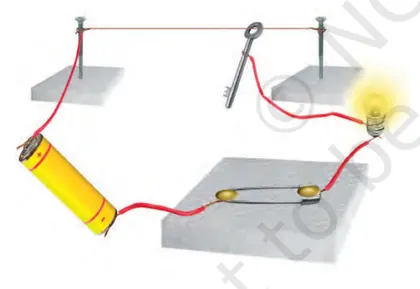
This chapter introduces electric current and its observable effects — heating, magnetic and chemical. Starting from simple circuits (cell, wires, bulb, switch, ammeter), students learn what electric current is, how to draw and assemble basic circuits, and how materials differ as conductors or insulators. The chapter explains the heating effect of current (why bulbs and heating elements get hot) and safe devices such as fuses; the magnetic effect (how current produces a magnetic field, making electromagnets and deflecting compasses) and practical applications (electric bells, motors); and the chemical effect (basic idea of electroplating and deposition). Importance: understanding these effects links electricity to everyday devices, safety and technology. By the end students will be able to construct and interpret simple circuits, describe and give examples of the three main effects of current, explain the working and purpose of a fuse, and appreciate safe handling and common applications of electric current.
Learning Objectives
- Define electric current and state its SI unit.
- Explain conventional direction of current and the actual flow of electrons in a conductor.
- Identify common circuit symbols and draw simple circuit diagrams using them.
- Construct simple series and parallel circuits using cells, bulbs, switches and wires, and record observations.
- Predict the relative brightness of bulbs when the number of cells or circuit arrangement (series/parallel) is changed.
- Distinguish between conductors and insulators with examples and justify their behavior in an electric circuit.
- Explain the heating effect of electric current with everyday examples and list factors that influence heating (current, resistance, time).
- Explain the magnetic effect of electric current and demonstrate how to make and use an electromagnet.
Topics in this chapter
12 topics · tap a topic title to jump straight to it.
Electric Current
What is Electric Current?
Electric current is the flow of electric charge through a conductor. In metals, this flow is due to the motion of free electrons. A current flows only when there is a closed path (circuit) and a source of electrical energy (like a cell or battery) that produces a potential difference (voltage) across the conductor.
Conventional direction and electron flow
By convention, electric current is said to flow from the positive terminal to the negative terminal of a source. In reality, electrons (which carry negative charge) move from the negative terminal to the positive terminal. Both descriptions are used: conventional current (positive → negative) is what most circuit diagrams show, while electron flow is negative → positive.
SI unit and basic formula
The SI unit of electric current is the ampere (A). If a total charge Q (in coulombs, C) passes through a cross-section of a conductor in time t (in seconds), the average current I is:
- I = Q / t
- 1 A = 1 C s⁻¹
What a circuit needs for current to flow
- A source of potential difference (cell or battery)
- A closed conducting path (wires, components)
- A load (lamp, motor, resistor) that uses electrical energy
- A switch to open or close the circuit
How current is measured
Current is measured by an ammeter connected in series with the circuit element whose current is to be measured. The ammeter must have low internal resistance so it does not significantly change the current.
Factors affecting current
For a given source, the amount of current that flows depends on:
- the potential difference (voltage) across the conductor — higher voltage tends to give higher current,
- the material and dimensions of the conductor — good conductors (copper, aluminium) allow more current; longer or thinner wires carry less current,
- temperature — in many conductors, resistance increases with temperature and current decreases for the same voltage.
Relation with resistance and simple law (for many conductors)
Many metallic conductors behave according to Ohm's law (introduced simply at this stage): the current I through a conductor is directly proportional to the voltage V across it when temperature is constant. This is often written as V = I R, where R is the resistance. (Class 7 focus is on the idea that voltage drives current and that the material and size of the conductor resist it.)
Why electric current matters (effects)
Current produces useful effects that are used in everyday devices: the heating effect (electric heaters, filament bulbs), the magnetic effect (electric bells, motors, electromagnets), and the chemical effect (electroplating, electrolysis). Understanding current helps explain how electrical appliances work and how to use electricity safely.
Safety note
Even small voltages can be dangerous if current passes through the human body. Always avoid touching live wires and use proper insulation, fuses, and switches in circuits.
- Torch/flashlight: Battery provides potential difference; current flows through bulb filament to produce light.
- Electric kettle: Large current through heating element produces heat (heating effect of current).
- Charging a mobile phone: Current from charger flows into the phone battery to store energy.
- Electric bell: Current through a coil creates a magnetic effect that moves a hammer to ring the bell.
- Electroplating: Current causes metal ions to deposit on a surface (chemical effect).
- Household lighting and fans: Current supplied from mains powers bulbs and motors.
- I = Q / t (Current = charge passed / time taken)
- Q = I × t (Charge = current × time)
- 1 A = 1 C / s (One ampere equals one coulomb per second)
- V = I × R (Ohm's law — voltage = current × resistance, valid for many conductors at constant temperature)
- P = V × I (Electric power = voltage × current)
- P = I² × R (Power dissipated as heat in a resistor)
Electric Circuit and Circuit Diagrams
What is an electric circuit? An electric circuit is a closed path made of conductors through which electric charges (current) can flow. For current to flow, the circuit must be complete (closed) and there must be a source of electric energy (a cell or battery).
Basic components
- Cell/battery: provides electric potential (voltage).
- Conducting wires: connect components and allow charge to flow.
- Load (resistor, bulb): device that uses electrical energy (e.g., lamp, motor).
- Switch: opens or closes the circuit to stop or allow current.
- Ammeter: measures current (connected in series).
- Voltmeter: measures voltage across a component (connected in parallel).
- Fuse/earth/insulation: safety components to prevent damage or electric shock.
Open vs closed circuit: In a closed circuit (switch closed), current flows and devices like bulbs light up. In an open circuit (switch open), the path is broken and current stops.
Circuit diagrams and symbols are simple drawings that use standard symbols to show how components are connected. Common symbols: cell (short and long line), battery (group of cells), bulb (circle with cross), switch (break in line), wire (line), ammeter (A in a circle), voltmeter (V in a circle), resistor (zigzag) and ground/earth.
Types of connections (basic idea)
- Series connection: Components connected end-to-end in a single path. Current is same through all components; total resistance increases (R_total = R1 + R2 + ...).
- Parallel connection: Components connected on separate branches across the same two points. Voltage across each branch is the same; total resistance is less than any branch (1/R_total = 1/R1 + 1/R2 + ...).
Conventional current direction is taken from the positive terminal of the cell to the negative terminal (this is the direction used in most circuit diagrams).
Important practical notes: Always connect an ammeter in series and a voltmeter in parallel. Using the wrong connection can damage the instruments. Switches are used to control devices and safety elements (like fuses and earthing) protect circuits from excessive current.
- A torch (flashlight): a cell, a bulb, a switch and connecting wires form a simple closed circuit; opening the switch stops the bulb.
- Doorbell/buzzer: a switch (push-button), a battery and the bell/buzzer form a circuit; pressing the button closes the circuit and current energises the buzzer.
- Household lighting: lights and sockets are usually wired in parallel so each lamp gets full voltage and one lamp can be turned off without switching off others.
- Series string of old holiday lights: if one bulb fuses in a simple series string, the circuit opens and all lights may go off (illustrates series connection effect).
- A simple school circuit for experiments: cell, connecting wires, bulb holder, bulb and a switch used to study brightness changes when cells are added.
- Electric current: I = Q / t, where I is current (ampere, A), Q is charge (coulomb, C) and t is time (second, s).
- Series resistors: R_total = R1 + R2 + ...
- Parallel resistors: 1 / R_total = 1 / R1 + 1 / R2 + ...
- Ohm’s law (introduced later but useful): V = I × R (Voltage = Current × Resistance); units: V (volt), I (ampere), R (ohm, Ω).
Conductors and Insulators
What are conductors and insulators?
Conductors are materials that allow electric charge (usually electrons) to flow easily through them. Examples include metals like copper, aluminium and silver. Insulators are materials that do not allow electric charge to flow freely; they resist the movement of electrons. Examples include rubber, glass, plastic and dry wood.
Why do they behave differently?
- Conductors: In conductors, some electrons (called free or delocalised electrons) are not tightly bound to atoms. When an electric potential (voltage) is applied, these electrons move and form an electric current.
- Insulators: In insulators, electrons are tightly bound to atoms and cannot move freely. This prevents a steady flow of charge when voltage is applied.
Important points:
- Metals are generally good conductors because of many free electrons in their atomic structure.
- Non-metallic solids (rubber, glass, plastic) are good insulators because their electrons are bound tightly to atoms.
- Some substances (like graphite and certain semiconductors) show intermediate behaviour — graphite conducts, diamond (both forms of carbon) does not.
- Temperature affects conductivity: for most metals, resistance increases with temperature; for some semiconductors, conductivity increases with temperature.
Practical uses: Conductors are used for wiring and connections to carry current (e.g., copper wires). Insulators are used to cover wires, handle electrical switches safely, and to separate charged parts (e.g., PVC covering, ceramic insulators on pylons).
Safety note: Even good insulators can become conductive when exposed to very high voltages, wetting or damage. Always follow safety rules around electricity.
- Copper wire used in household electrical wiring — conductor
- Aluminium cookery utensils — conductor (gets hot when current passes through)
- Rubber gloves used by electricians — insulator (protects against shocks)
- PVC or rubber covering on wires — insulator (prevents accidental contact)
- Glass or ceramic insulators on power-line poles — insulator (supports live wires safely)
- Graphite in pencil lead — conductor (used in some electrodes)
- Current: I = Q / t (current I is charge Q passing a point in time t)
- Ohm's law (for many conductors): V = I R (voltage = current × resistance)
- Resistance of a conductor: R = ρ × (L / A) (ρ is resistivity, L is length, A is cross-sectional area)
- Conductivity: σ = 1 / ρ (σ is electrical conductivity; high σ = good conductor)
- Power (heating effect): P = V I = I^2 R = V^2 / R
Series and Parallel Connections
What are series and parallel connections?
Series connection: Components (bulbs, resistors, cells) are said to be in series when they are connected end-to-end so that there is only one path for current to flow. The same current passes through each component. If one component in the path breaks, the whole circuit stops working.
Parallel connection: Components are in parallel when they are connected across the same two points so that there are multiple paths for current. Each component has the same voltage across it. If one component fails, the others can still work because current can flow through the remaining branches.
Key characteristics
- Current: In series the current is the same through all components. In parallel the total current is the sum of currents through each branch.
- Voltage: In series the total voltage across the series is the sum of voltage drops across components. In parallel each branch has the same voltage equal to the supply voltage.
- Resistance: Series resistances add; parallel resistances combine to give a smaller equivalent resistance.
Why it matters
Brightness of bulbs, safety and reliability of circuits, and total resistance depend on how components are connected. For example, household wiring uses parallel connections so each appliance gets full voltage and one appliance can be switched off without affecting others. Old Christmas-lights used series wiring so one blown bulb turned the whole string off.
How to identify
- Series: single loop, components arranged one after another, single current path.
- Parallel: multiple loops or branches joining the same two nodes, each component has two common connection points.
Simple numeric idea
Two identical bulbs/resistors of resistance R connected in series give equivalent resistance 2R, so current from a fixed battery reduces. The same two in parallel give equivalent resistance R/2, so current from the battery increases (but split between branches).
- Christmas tree lights (old series strings where one bulb failing causes the whole string to go out).
- Flashlight (torch) batteries in series to increase voltage for the bulb.
- Household wiring: lights, fans and outlets connected in parallel so each appliance gets full supply voltage and operates independently.
- Car electrical system: headlights, radio and dashboard circuits are wired in parallel branches from the battery.
- Street lamps on separate parallel branches so one lamp failing does not turn off others.
- Ohm's law: V = I * R
- Series equivalent resistance: R_eq = R1 + R2 + R3 + ...
- Parallel equivalent resistance: 1 / R_eq = 1 / R1 + 1 / R2 + 1 / R3 + ...
- Two-resistor parallel shortcut: R_eq (two) = (R1 * R2) / (R1 + R2)
- Series current: I_series = I1 = I2 = ...
- Series voltage drops: V_total = V1 + V2 + ... and V_i = I * R_i
Measuring Current and Potential Difference
Electric current is the flow of electric charge. At Class 7 level we define electric current (I) as the amount of charge (Q) passing through a cross-section of a conductor per unit time (t):
I = Q / t
Its SI unit is ampere (A). The conventional direction of current is from the positive terminal to the negative terminal of a battery.
Potential difference (p.d.) or voltage between two points is the work done to move a unit positive charge from one point to the other. It tells us how strongly charges are pushed through a circuit element. Mathematically:
V = W / Q
Its unit is volt (V).
Instruments to measure:
- Ammeter: measures current in amperes. It must be connected in series with the component whose current you want to measure so all the charge flowing through the component also flows through the ammeter. A good ammeter has very low internal resistance so it does not change the current significantly.
- Voltmeter: measures potential difference in volts. It must be connected in parallel across the two points whose p.d. is to be measured. A good voltmeter has very high internal resistance so it draws very little current and does not change the circuit conditions.
How to measure current (step-by-step):
- Switch off the circuit before changing connections.
- Open the circuit at a point in the path of current and insert the ammeter so that current flows through the ammeter (series connection).
- Turn on the circuit and read the ammeter scale.
How to measure potential difference (step-by-step):
- Switch off the circuit before changing connections.
- Connect the voltmeter's two terminals across (in parallel with) the component or two points whose voltage you want to measure.
- Turn on the circuit and read the voltmeter scale.
Important safety/tips:
- Never connect an ammeter directly across a battery or supply (i.e., in parallel) — it will short the supply because of its low resistance and may get damaged.
- Do not put a voltmeter in series — its high resistance would prevent current from flowing and give wrong readings.
- Multimeters can act as either ammeter or voltmeter; follow correct settings and wiring.
Relation to Ohm's law (simple connection):
For many conductors (ohmic conductors), the potential difference across the conductor is proportional to the current through it:
V = I R
where R is the resistance (unit: ohm, Ω).
Putting it together: To study a circuit practically, students use an ammeter in series to find current values and a voltmeter in parallel to find potential differences, then apply formulas (I = Q/t, V = W/Q, V = IR) to interpret results.
- Measuring the current through a bulb: Insert the ammeter in series with the bulb; the ammeter shows how much current flows when the bulb is on (e.g., 0.2 A).
- Measuring the voltage of a cell/battery: Connect the voltmeter across the battery terminals; a fresh 1.5 V cell reads close to 1.5 V.
- Using a voltmeter to measure the p.d. across a resistor in a circuit: Connect the voltmeter across the resistor and read the voltage drop while the circuit is powered.
- Using a multimeter: Set to the correct range and connect probes correctly (amperes in series, volts in parallel) to avoid damage.
- I = Q / t (Current = charge ÷ time) — unit: ampere (A)
- V = W / Q (Potential difference = work done ÷ charge) — unit: volt (V)
- V = I R (Ohm's law: voltage = current × resistance) — R in ohms (Ω)
- P = V I (Electric power = voltage × current) — unit: watt (W)
Heating Effect of Electric Current
What it is
The heating effect of electric current means that whenever electric current flows through a conductor, some electrical energy is converted into heat energy. This happens because moving electrons collide with the atoms (ions) of the conductor and transfer energy to them. The increased vibrational energy of atoms is felt as heat.
Why it happens (simple explanation)
In a conductor, electric current is a flow of electrons. As electrons move, they bump into fixed positive ions in the metal. These collisions slow electrons down and transfer kinetic energy to the ions, making them vibrate more. Increased vibration raises the temperature of the material.
Factors that affect heating
- Current (I): Heating rises rapidly with current. If current doubles, heating increases by four times (since heat ∝ I²).
- Resistance (R): For a given current, a higher resistance produces more heat. For a fixed voltage source, higher resistance gives less current and so may produce less heat.
- Time (t): Longer time of current flow produces more heat (heat ∝ time).
Joule's law (class 7 level)
The heat produced (H) in a conductor due to current for time t is given by: H ∝ I²Rt. The precise relation commonly used is H = I² R t. Using Ohm's law (V = IR) we can also write H = V I t or H = V² t / R. Here H is heat energy (in joules), I is current (in amperes), R is resistance (in ohms) and t is time (in seconds).
Important points
- Heating effect can be useful (electric iron, kettle) or harmful (overheating, fuse blowing).
- Thin wires with high resistance heat more for the same current and may melt or burn; this principle is used in fuses which protect circuits.
- Incandescent bulbs produce light because the filament gets very hot; much electrical energy becomes heat (and some light).
Safety note
Excessive heating can cause fires or damage. Always use correct fuse ratings, insulation and avoid overloading sockets.
- Electric iron: electric current passes through the high-resistance heating element and produces heat to press clothes.
- Electric kettle or geyser: current through a heating coil raises water temperature quickly.
- Toaster: metal coils heat up and toast bread by converting electrical energy into heat.
- Incandescent bulb: current heats the thin tungsten filament until it glows, producing light and heat.
- Fuse: a thin wire melts when too much current flows, breaking the circuit to prevent overheating and fire.
- Joule's law: H = I^2 R t (Heat produced in time t)
- Using V = IR: H = V I t (work done by the source)
- Also: H = V^2 t / R (derived from H = I^2 R t and I = V / R)
- Units: H in joules (J). 1 calorie = 4.186 J (useful when measuring heat in calories)
Electric Fuse and Short Circuit
Short Circuit
A short circuit is an unintended low-resistance connection between two points of different potential (for example between the live and neutral wires). Because the resistance of this path is very small, a very large current flows. This sudden large current causes excessive heating, sparks, fires and may damage appliances and wiring.
- Cause: damaged insulation, exposed wires touching, loose connections, or faulty appliances.
- Effect: large current surge, heating, possible fire, and damage to devices.
Electric Fuse
A fuse is a simple protective device put in series with a circuit (usually in the live wire). It contains a thin wire (the fuse element) made of a metal/alloy with a relatively low melting point. When current in the circuit exceeds the fuse's rated value, the heat produced (by the current) melts the fuse wire and opens the circuit, stopping the current flow. This protects wiring and appliances from damage.
- Construction: thin fuse wire inside a non‑combustible casing (glass or ceramic) with end caps to hold contacts.
- Placement: always in series with the live (phase) wire so that when it blows the appliance is disconnected from the supply.
- Rated current: the maximum current the fuse will carry indefinitely without melting (e.g., 1 A, 5 A, 15 A).
- Working principle: Fuse operates due to Joule heating — heat produced in the fuse element is H = I²Rt; if the heat raises the element to its melting temperature, the wire melts and the circuit opens.
Difference between overload and short circuit
- Overload: Many devices together draw current higher than the safe rating; current rises moderately and may take time to blow a fuse.
- Short circuit: A near-zero resistance path causes an immediate, very large current surge; a fuse blows very quickly.
Practical points & safety
- Always replace a blown fuse with one of the correct rated current — never with a higher rating or a shorting link.
- Do not bypass the fuse; it prevents fires and equipment damage.
- Modern homes often use MCBs (Miniature Circuit Breakers) which can be reset; fuses must be replaced after they blow.
- A hair-dryer shorting because water enters the appliance — causes sparks and blows the fuse.
- Two exposed wires in a lamp touching each other — creates a short circuit and trips the fuse.
- Plugging too many high-power appliances into one socket (overloading) — fuse blows to protect the wiring.
- Rodent chewing insulation leading to live and neutral touching — short circuit and fuse operation.
- Old appliance with internal fault connecting live and metal body — huge current flows and the fuse blows.
- Replacing a blown fuse with a wire or higher-rated fuse — dangerous practice that can cause fire (do not do this).
- Ohm's law: V = I × R (Voltage = Current × Resistance)
- Joule's heating (heat produced in time t): H = I² × R × t (shows heating grows with square of current)
- Power dissipated in a resistor: P = V × I = I² × R = V² / R
- Short-circuit current (approx): I_short ≈ V / R_short (if R_short is very small, I_short is very large)
Magnetic Effect of Electric Current
What it means
When an electric current flows through a conductor, it produces a magnetic field around the conductor. This phenomenon is called the magnetic effect of electric current. It shows that electricity and magnetism are closely related.
Key experiments and observations
- Oersted's experiment: A compass needle kept near a current-carrying wire gets deflected. This demonstrated that current produces a magnetic field.
- Shape of the magnetic field: For a straight current-carrying wire, magnetic field lines are concentric circles around the wire. For a circular loop, field lines are curved and pass through the center. For a long solenoid (coil), field lines inside are nearly straight and strong (like a bar magnet), while outside they are similar to a bar magnet's field.
- Electromagnet: A soft iron core inside a coil carrying current becomes strongly magnetic. The strength depends on current and number of turns.
Direction of the magnetic field
Use these simple rules to find direction:
- Right-hand thumb rule (for straight wire): If you hold the wire with your right hand so that your thumb points in the direction of current, your fingers wrapped around the wire show the direction of magnetic field lines (circles around wire).
- Right-hand grip rule (for a coil/solenoid): If you curl the fingers of your right hand in the direction of current in the coil, your thumb points to the north pole of the coil (direction of magnetic field inside).
- Fleming's left-hand rule (for force on a current-carrying conductor in a magnetic field): Useful for motors — index finger = direction of magnetic field, middle finger = direction of current, thumb = direction of force (motion).
Why it matters
Magnetic effect of current is the principle behind many devices: electric motors, loudspeakers, electric bells, relays, electromagnets used in cranes, and more. It explains how electricity can produce motion (motors) or create controllable magnets.
Important points
- Stronger current or more turns in a coil makes a stronger magnetic field.
- Magnetic field strength decreases with distance from the wire.
- A soft iron core increases the magnetic field of a coil by becoming magnetised while the current flows.
Simple classroom demonstrations: Move a compass near a current-carrying wire to see deflection; wrap a coil around an iron nail and connect to a battery to pick up paper clips (electromagnet); place a small magnet near a coil with current to observe attraction or repulsion.
- Electric bell: Current through a coil makes an electromagnet which attracts a hammer to strike the bell.
- Loudspeaker: Current in a coil placed in a magnetic field causes the coil (and cone) to move, producing sound.
- Electric motor: Current in coils within a magnetic field experiences force and produces rotation.
- Electromagnetic crane: Large current through coils magnetises cores to pick up scrap metal; switching off current releases it.
- Relay and solenoids in circuits: Small current can operate a switch or move a mechanical part using electromagnetic effect.
- Magnetic field around long straight wire: B = μ0 * I / (2πr) (B in tesla, I in ampere, r is distance from wire).
- Magnetic field inside a long solenoid: B = μ0 * n * I (n = number of turns per unit length, I = current).
- Force on a current-carrying conductor in a magnetic field: F = B * I * L * sinθ (L = length of conductor in field, θ = angle between B and current direction).
- Permeability of free space: μ0 = 4π × 10^-7 T·m/A (useful constant for calculations)
Electromagnets and Solenoids
What is a solenoid? A solenoid is a long coil of insulated wire wound in many turns (loops). When an electric current passes through the coil, it produces a magnetic field. The field inside a long solenoid is nearly uniform and its outside field resembles that of a bar magnet.
What is an electromagnet? An electromagnet is a solenoid with a soft iron (or similar ferromagnetic) core placed inside it. The iron core strengthens the magnetic field produced by the solenoid. Unlike a permanent magnet, an electromagnet can be switched on and off by controlling the electric current.
How it works (simple explanation):
- Electric current in each turn of the wire produces a small magnetic field. The fields from all turns add up, giving a strong net field.
- Inside the solenoid the field lines are nearly straight and parallel (similar to the field of a bar magnet from south to north inside the magnet), making the region inside act like the strong pole of a magnet.
- Putting a soft iron core inside increases the magnetic field because the iron becomes magnetised by the solenoid and its relative permeability is much greater than air.
- The direction of the magnetic poles of the solenoid can be found by the right-hand rule for coils: if the curled fingers follow the direction of current, the thumb points to the solenoid’s north pole.
Factors affecting strength of an electromagnet/solenoid:
- Current (I): greater current → stronger magnetic field.
- Number of turns (N): more turns → stronger field (for same current).
- Length of the coil (L): for a given N, a shorter coil (larger turns per unit length) increases field inside.
- Core material: soft iron or ferromagnetic cores increase the field (relative permeability μr > 1).
Key differences—solenoid vs electromagnet:
- Solenoid = coil of wire (may have air core). Electromagnet = solenoid + magnetic core that enhances the field.
- Solenoid demonstrates the magnetic effect of current; electromagnet is used where a controllable magnet is needed.
- Electric bell: a coil (electromagnet) attracts a hammer to strike the bell when current flows, then the circuit breaks and repeats.
- Scrap-yard crane: a large electromagnet lifts and releases heavy metal pieces by switching current on and off.
- Door lock (electromagnetic lock) and relays: electromagnets operate locks and switch circuits.
- Loudspeakers: voice coils (solenoids) interact with permanent magnets to move the speaker cone and produce sound.
- Magnetic separation: electromagnets help separate magnetic materials from non-magnetic waste in industries.
- MRI (medical imaging) and devices: large electromagnets produce controlled strong magnetic fields (conceptually advanced example).
- Magnetic field inside an ideal long solenoid: B = μ0 * n * I, where n = N/L (turns per metre), μ0 = 4π × 10^-7 H/m.
- With a magnetic core: B = μ * n * I, where μ = μ0 * μr (μr is the relative permeability of the core material).
- Turns per unit length: n = N / L (N = total turns, L = length of solenoid in metres).
- Force on a current-carrying conductor in a magnetic field (useful related formula): F = B * I * l (for a conductor of length l perpendicular to field B).
Applications of Electromagnetism and Heating Effect
Overview
Electromagnetism: When electric current flows through a coil of wire, a magnetic field is produced around the coil. If the coil is wound on a soft iron core, the core becomes magnetised and the assembly is called an electromagnet. The magnetism exists only when current flows.
Key factors that affect an electromagnet
- Electric current: stronger current → stronger magnetic field.
- Number of turns in the coil: more turns → stronger field.
- Core material: soft iron core increases strength and loses magnetism quickly when current stops.
Applications of electromagnetism
Electromagnets are used where magnetic force needs to be switched on and off or varied. Examples include electric bells (the armature is attracted when current flows), relays and solenoid switches (to open/close circuits), electric motors and generators (interaction of current and magnetic fields produces motion or electricity), loudspeakers (varying current makes a diaphragm move and produces sound), and scrapyard cranes (electromagnets pick up heavy ferrous materials).
Heating effect of electric current (Joule heating)
When current flows through a conductor, collisions between moving charges and the atoms of the conductor produce heat. The amount of heat produced depends on current, resistance, and time. This heating effect is useful in many appliances but can be harmful if uncontrolled (causes fires or melts wires).
Applications of heating effect
Common uses rely on converting electrical energy into heat: electric heaters, electric iron, geysers and water heaters, toasters, electric stoves, filament of incandescent bulbs (glow due to heating), soldering irons, and fuses (designed to melt and break the circuit when excessive current flows).
Safety and control
Because both electromagnetism and heating effects can be hazardous or damaging, devices use fuses, circuit breakers, proper insulation, and earthing. Fuses exploit the heating effect: an oversized current melts the thin fuse wire and breaks the circuit preventing further damage.
- Electric bell: When the circuit is made, the coil becomes an electromagnet and attracts the hammer; when the hammer moves, the circuit breaks and the hammer falls back, repeating the process to ring the bell.
- Scrapyard crane: A large electromagnet is switched on to pick up iron scrap and switched off to drop it at the desired place.
- Electric iron and heater: Electric current passing through a resistive element heats it; the heat is transferred to clothes or air.
- Fuse in household wiring: Excessive current produces sufficient heat to melt the fuse wire, breaking the circuit and preventing fire.
- Loudspeaker: Varying current through a coil near a magnet causes the coil and attached cone to move, producing sound.
- Electric power (instantaneous): P = V × I
- Power in terms of current and resistance: P = I^2 × R
- Power in terms of voltage and resistance: P = V^2 / R
- Heat (energy) produced in time t (Joule's law): H (or Q) = I^2 × R × t
- Proportional form (Joule's law): H ∝ I^2 × R × t
Safety Precautions with Electricity
Why safety with electricity is important
Electric current is very useful but can be dangerous. It can give electric shocks, cause burns, start fires or damage appliances. Even small currents through the human body can be harmful. Knowing and following safety precautions reduces these risks.
Basic safety rules
- Always keep electrical appliances, plugs and switches dry. Do not touch them with wet hands.
- Do not use damaged or frayed wires. Replace cords with cracked insulation.
- Do not overload a socket. Plugging many high-power devices into one socket may heat the wires and cause a fire.
- Switch off appliances and the main switch before repairing or replacing parts (for example, changing a bulb).
- Use appliances according to their rating. Match the voltage and current ratings on the appliance and fuse or plug.
- Use three-pin plugs with earthing (the third pin). Earthing gives a low-resistance path for fault current and reduces the risk of electric shock.
- Use insulated tools and handles. Avoid inserting metal objects (nails, knives) into sockets or devices.
- Keep electrical appliances away from water sources (sinks, bathtubs) and avoid using extension cords across wet floors.
- During storms or lightning, unplug sensitive electronics to avoid damage from power surges.
- Teach children that they must not play with switches, plugs, sockets or electrical equipment.
Protection devices
- Fuse: A fuse is a thin wire placed in series with a circuit. If the current exceeds the fuse rating, the wire melts and opens the circuit, preventing overheating and fires. Fuses must be replaced with the correct rating.
- Circuit breaker: A reusable switch that automatically opens when current becomes too large. It can be reset after the fault is cleared.
- Earthing: The earth wire provides a safe path for fault current to flow to the ground, preventing the metal body of an appliance from becoming live.
- Residual Current Device (RCD) / Earth Leakage Circuit Breaker (ELCB): Detects small leakage currents to earth and quickly disconnects power to reduce the risk of fatal shock.
What to do in case of an electric shock
- Do not touch the person who is being shocked if they are still in contact with the live source.
- Switch off the mains power immediately, if it is safe to do so. If you cannot switch off power, use a dry wooden stick or non-conducting object to separate the person from the source.
- Call emergency services and seek medical help right away.
- If the person is unconscious and not breathing, trained rescuers may begin CPR after the person is free from the electrical source.
Simple checks and good habits
- Fit three-pin plugs with the correct fuse for appliances (e.g., low-power devices use lower fuse ratings).
- Have regular electrical inspections at home to check wiring, sockets and earthing.
- Use MCBs/RCDs for added protection where available.
- Store and use appliances according to manufacturer instructions and avoid makeshift repairs.
Conclusion
Basic awareness, correct fitting of protective devices (fuses, earthing, circuit breakers), and sensible habits (dry hands, no overloading, prompt repair of faults) keep electricity useful and safe.
- Do not use a hair dryer with wet hands or while standing on a wet bathroom floor — water increases risk of electric shock.
- If many lights and a heater are connected to a single outlet and the fuse blows, it prevented wires from overheating and a possible fire.
- A three-pin plug with earthing prevents the metal body of a cooker from becoming live when an internal fault occurs.
- Unplugging a TV or computer during a thunderstorm protects it from voltage spikes and lightning-induced surges.
- A child inserting a metal object into a wall socket can be saved by the socket cover or by teaching children not to touch electrical outlets.
- V = I × R — Ohm's law (Voltage = Current × Resistance). Use to calculate current flowing through a device.
- P = V × I — Electrical power (Power = Voltage × Current). Use to estimate how much current an appliance draws: I = P / V.
- E = P × t — Electrical energy consumed (Energy = Power × time). Helps estimate total load over time.
- Fuse selection guideline: I_fuse ≈ 1.25 × I_normal (choose a fuse slightly above normal working current so it does not blow under normal surges).
- Total current for multiple devices: I_total = I1 + I2 + ... + In. Ensure I_total is less than the socket or circuit rating to avoid overloading.
Energy Conversion and Everyday Examples
When an electric current flows through a device, the electrical energy is converted into other forms of energy depending on the device's construction and purpose. The main types of conversions seen in everyday electrical devices are:
- Electrical → Heat (Joule heating): Current through a resistive element (wire, heating coil) produces heat. This is used in electric heaters, irons and toasters.
- Electrical → Light: In lamps and bulbs electrical energy is converted into light (and some heat). Incandescent bulbs waste much energy as heat, while LEDs convert a larger fraction into light.
- Electrical → Mechanical: Electric motors convert electrical energy into mechanical energy (motion). Examples: fans, mixers, refrigerator compressors.
- Electrical → Magnetic: Current through a coil creates a magnetic field (electromagnet). This magnetic effect is used in bells, relays and loudspeakers.
- Electrical → Chemical: Current can cause chemical changes (electrolysis) or charge batteries: charging a battery stores electrical energy as chemical energy.
- Electrical → Sound: Devices like buzzers and speakers convert electrical energy into sound (often via magnetic/mechanical effects).
Key ideas to remember:
- Most devices convert electrical energy into more than one form (for example, a filament bulb makes both light and heat).
- Energy conversion efficiency tells how much electrical energy becomes useful output (for a bulb, useful output is light). Efficiency = (useful energy out / total electrical energy in) × 100%.
- Joule heating (thermal energy produced by current in a resistor) is useful in heaters but is wasted energy in devices that should produce light or motion.
- Safety devices (fuses, MCBs) protect circuits by stopping current when too large a current would cause dangerous heating.
This topic helps students identify what energy changes occur in appliances at home and how to compare devices (for example, LED vs filament bulbs) using energy consumption and efficiency.
- Electric bulb (incandescent): Electrical → Light + Heat (most energy lost as heat).
- LED bulb: Electrical → Light (much higher efficiency, less heat than filament bulbs).
- Electric heater/room heater/immersion rod: Electrical → Heat (uses Joule heating to raise temperature).
- Electric iron/toaster: Electrical → Heat used for ironing/toasting (Joule heating in coils).
- Ceiling fan/electric motor in mixer: Electrical → Mechanical (rotating motion) and some heat loss.
- Electric bell: Electrical → Magnetic (electromagnet pulls striker) → Mechanical → Sound.
- Ohm's law: V = I × R (Voltage = Current × Resistance). Units: V (volts), I (amperes), R (ohms).
- Electric power: P = V × I (Power in watts = voltage × current).
- Power using resistance: P = I^2 × R = V^2 / R (useful for heating calculations).
- Energy (electrical) consumed: E = P × t (Energy in joules = Power × time in seconds).
- Common energy unit for homes: E (kWh) = P (kW) × t (hours) — 1 kWh = 3,600,000 J.
- Heat produced by current (Joule's law): H (J) = I^2 × R × t.
Key Concepts
- Electric current
- Flow of electric charge (usually electrons) through a conductor, measured in amperes (A).
- Circuit
- A closed path made of conductors through which electric current can flow.
- Conductor
- Material that allows easy flow of electric current due to free electrons (e.g., metals).
- Insulator
- Material that resists the flow of electric current and prevents charge movement.
- Cell
- A single device that converts chemical energy into electrical energy and provides a voltage.
- Battery
- Two or more cells connected together to provide higher voltage or current capacity.
- Potential difference (Voltage)
- Work done to move a unit charge between two points; it drives current, measured in volts (V).
- Ammeter
- Instrument used to measure electric current; must be connected in series in a circuit.
- Voltmeter
- Instrument used to measure potential difference between two points; connected in parallel.
- Switch
- A device that can open (break) or close (complete) a circuit to stop or allow current flow.
- Resistance
- Property of a material that opposes the flow of current, measured in ohms (Ω).
- Fuse
- A safety device containing a thin wire that melts and breaks the circuit when current is excessive.
- Short circuit
- An unintended low-resistance path between two points of different potential causing large current flow.
- Heating effect of current (Joule heating)
- When current flows through a conductor, electrical energy is converted to heat in the conductor.
- Magnetic effect of current
- An electric current produces a magnetic field around the conductor, which can exert forces on magnets or other currents.
- Electromagnet
- A temporary magnet created by passing current through a coil wound around an iron core; strength depends on current and coils.
- Electric bell
- A device that uses an electromagnet to repeatedly strike a bell when current flows, producing sound.
- Filament bulb (Incandescent bulb)
- A bulb in which a thin metal filament glows and emits light when heated by electric current.
- Series circuit
- Circuit arrangement where components are connected end-to-end so the same current flows through each.
- Parallel circuit
- Circuit arrangement where components are connected across the same two points so each receives full voltage independently.
End-of-Chapter Trial Paper & Test Questions
Topic-wise questions to test your understanding of every concept in this chapter.
-
Which of the following is the SI unit of electric current? / विद्युत धारा की SI इकाई निम्नलिखित में से कौन सी है? (a) Volt / वोल्ट (b) Ohm / ओम (c) Ampere / एम्पियर (d) Watt / वाट
Show answer
(c) Ampere / एम्पियर — Electric current is defined as I = Q/t (charge per unit time) and its SI unit is the ampere (A). / विद्युत धारा की परिभाषा I = Q/t (प्रति इकाई समय आवेश) है और इसकी SI इकाई एम्पियर (A) है।
-
A fuse wire is connected in ______ with the circuit to protect it from excessive current. / फ्यूज तार को अत्यधिक धारा से बचाने के लिए परिपथ के साथ ______ में जोड़ा जाता है।
Show answer
series / श्रेणी — A fuse must be in series so that all current passes through it; when current exceeds the rated value, the fuse wire melts and breaks the circuit. / फ्यूज को श्रेणी में होना चाहिए ताकि सभी धारा उसमें से गुजरे; जब धारा निर्धारित मान से अधिक हो जाती है तो फ्यूज तार पिघल कर परिपथ तोड़ देती है।
-
When current flows through a wire, the wire gets hot. According to Joule's law, the heat produced H = ______. / जब धारा एक तार से प्रवाहित होती है तो तार गर्म हो जाता है। जूल के नियम के अनुसार उत्पन्न ऊष्मा H = ______। (a) I × R × t / I × R × t (b) I² × R × t / I² × R × t (c) V × t / V × t (d) R ÷ (I × t) / R ÷ (I × t)
Show answer
(b) I² × R × t / I² × R × t — Joule's law: H = I²Rt where I is current (A), R is resistance (Ω), and t is time (s). Heating is proportional to the square of the current. / जूल का नियम: H = I²Rt जहाँ I धारा (A), R प्रतिरोध (Ω) और t समय (सेकंड) है। ऊष्मा धारा के वर्ग के समानुपाती होती है।
-
True or False: In a series circuit, if one bulb burns out, all the remaining bulbs will still glow. / सत्य या असत्य: श्रेणी परिपथ में, यदि एक बल्ब जल जाए, तो शेष सभी बल्ब तब भी जलते रहेंगे।
Show answer
False / असत्य — In a series circuit there is only one path for current; if one component fails (open circuit), the whole circuit breaks and all bulbs go out. / श्रेणी परिपथ में धारा के लिए केवल एक पथ होता है; यदि एक घटक खराब हो जाए (खुला परिपथ) तो पूरा परिपथ टूट जाता है और सभी बल्ब बुझ जाते हैं।
-
Oersted's experiment demonstrated that a current-carrying wire produces ______ around it. / ओर्स्टेड के प्रयोग ने दर्शाया कि धारावाही तार अपने चारों ओर ______ उत्पन्न करती है।
Show answer
a magnetic field / एक चुंबकीय क्षेत्र — Oersted observed that a compass needle placed near a current-carrying wire was deflected, proving that current produces a magnetic field. / ओर्स्टेड ने देखा कि धारावाही तार के पास रखी एक कंपास सुई विक्षेपित हो गई, यह सिद्ध करते हुए कि धारा चुंबकीय क्षेत्र उत्पन्न करती है।
-
Give two everyday examples of the heating effect of electric current. / विद्युत धारा के ऊष्मीय प्रभाव के दो दैनिक जीवन के उदाहरण दीजिए।
Show answer
Electric iron (heating element heats up to press clothes) and electric kettle/geyser (heating coil boils water). / इलेक्ट्रिक आयरन (कपड़े प्रेस करने के लिए हीटिंग एलिमेंट गर्म होता है) और इलेक्ट्रिक केतली/गीज़र (हीटिंग कॉइल पानी उबालती है)।
-
An electromagnet can be made stronger by / एक विद्युत चुंबक को किस प्रकार अधिक शक्तिशाली बनाया जा सकता है? (a) Reducing the current / धारा कम करके (b) Reducing the number of turns of wire / तार के फेरों की संख्या कम करके (c) Increasing the current and number of turns, and using a soft iron core / धारा और फेरों की संख्या बढ़ाकर और मृदु लोहे की क्रोड उपयोग करके (d) Using an insulating core / एक कुचालक क्रोड उपयोग करके
Show answer
(c) Increasing the current and number of turns, and using a soft iron core / धारा और फेरों की संख्या बढ़ाकर और मृदु लोहे की क्रोड उपयोग करके — Greater current, more turns, and a soft iron core (which enhances the magnetic field due to its high permeability) all increase electromagnet strength. / अधिक धारा, अधिक फेरे, और मृदु लोहे की क्रोड (जो उच्च चुंबकशीलता के कारण चुंबकीय क्षेत्र को बढ़ाती है) सभी विद्युत चुंबक की शक्ति बढ़ाते हैं।
-
What is the difference between a conductor and an insulator? Give one example of each. / चालक और कुचालक (रोधक) में क्या अंतर है? प्रत्येक का एक उदाहरण दीजिए।
Show answer
A conductor allows easy flow of electric current (e.g., copper wire); an insulator does not allow current to flow (e.g., rubber). / चालक विद्युत धारा को आसानी से प्रवाहित होने देता है (जैसे, तांबे का तार); कुचालक धारा को प्रवाहित नहीं होने देता (जैसे, रबर)।
Related Laws & Principles
Explore allFoundational laws & principles behind this chapter. Each one opens a full page — what it says, why it matters, five practice questions and the mistakes to avoid.