Overview
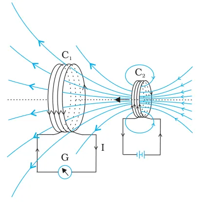
This chapter introduces electromagnetic induction — the production of an electromotive force (emf) in a circuit due to a changing magnetic environment. Starting from Faraday’s experiments and Faraday’s law (ε = -dΦ/dt) and Lenz’s law (direction of induced emf opposes change), students learn the physical basis of induced currents and motional emf (ε = Bℓv). The chapter develops flux and flux linkage concepts, shows how a changing magnetic flux produces non‑conservative electric fields, and treats self‑induction (L), mutual induction (M) and the energy stored in magnetic fields (U = 1/2 LI^2). Key applications and experiments — eddy currents and their effects, simple AC generators (εmax = NBAω) and practical devices based on induction — are discussed to connect theory with technology (generators, induction cookers, transformers and braking systems). Importance: electromagnetic induction is central to modern electrical power generation, transformers, many measurement techniques and electromechanical devices; understanding it builds skills in mathematical derivation, vector reasoning and problem solving required in CBSE Class 12 Physics. By the end of the chapter the student will be…
Learning Objectives
- Define magnetic flux and state its SI unit
- Explain Faraday's laws of electromagnetic induction and Lenz's law with illustrative examples
- Derive the expression for induced emf in a coil due to a time-varying magnetic flux (Faraday's law)
- Apply Faraday's law and Lenz's law to determine the magnitude and direction of induced emf/current in simple circuits
- Calculate motional emf and induced current for a conductor moving in a magnetic field
- Solve numerical problems involving changing magnetic flux, induced emf, and induced current in single and multi-turn coils
- Describe self-inductance and derive the expression for emf induced in an inductor when the current changes
- Calculate the energy stored in an inductor and interpret its physical significance
Topics in this chapter
16 topics · tap a topic title to jump straight to it.
Magnetic Flux
Definition: Magnetic flux (Φ) through a surface is a measure of the total magnetic field passing through that surface. For a surface element dA with magnetic field B, the flux is defined as the surface integral
Φ = ∫_S B · dA = ∫_S B cosθ dA
For a uniform magnetic field B and a flat surface of area A whose normal makes an angle θ with B, this reduces to
Φ = B A cosθ
Area vector: The direction of the area vector is perpendicular to the surface (given by the right-hand rule for loops). If B is perpendicular to the plane (θ=0), flux is maximum; if B is parallel to the plane (θ=90°), flux is zero.
Units: The SI unit of magnetic flux is the weber (Wb). 1 Wb = 1 T · m2 (tesla·square metre).
Flux linkage: For a coil of N closely wound turns, the flux linkage is NΦ. This quantity appears in Faraday's law of electromagnetic induction.
Faraday's law (basic): A changing magnetic flux through a circuit induces an emf (electromotive force) in the circuit. In integral form for a coil with N turns:
ε = - N (dΦ/dt)
The negative sign is Lenz's law: the induced emf produces a current whose magnetic effect opposes the change in flux.
Simple examples and special cases:
- Uniform field, fixed area, changing angle (e.g., rotating loop): Φ(t)=B A cos(ωt). Then ε = -N dΦ/dt = N B A ω sin(ωt) (AC output of a generator).
- Non-uniform field: compute Φ by Φ = ∫_S B(&rvec;) · dA.
Physical significance: Magnetic flux quantifies how strongly magnetic field lines thread a given area. Only a time-varying flux (or relative motion altering flux) produces an induced emf.
- AC generator: a coil rotates in a magnetic field so the magnetic flux through the coil varies as Φ(t)=BA cos(ωt), producing an alternating emf with amplitude N·B·A·ω.
- Transformer: an alternating current in the primary produces a changing flux in the iron core, which links the secondary and induces voltage according to the ratio of turns.
- Moving a bar magnet through a coil: changing flux through the coil induces a measurable emf and current (classic classroom experiment).
- Bicycle dynamo: rotating wheel changes flux through the generator coil, producing current to light the lamp.
- Induction cooktop/wireless charging: time-varying magnetic flux in a primary coil induces currents (or voltages) in nearby conductors/coils.
- Magnetic flux (general): Φ = ∫_S B · dA
- Uniform B, flat area: Φ = B A cosθ
- Flux linkage for N turns: Λ = N Φ
- Faraday's law (emf): ε = - d(N Φ)/dt = -N (dΦ/dt)
- Rotating coil (Φ(t)=B A cos(ωt)): ε(t) = -N dΦ/dt = N B A ω sin(ωt); ε_max = N B A ω
- SI unit: 1 Wb = 1 T·m²
Faraday's Law of Electromagnetic Induction
Statement: Faraday's law of electromagnetic induction states that the magnitude of the induced emf (electromotive force) in a circuit is equal to the rate of change of magnetic flux through the circuit. The direction of the induced emf is such that it opposes the change of flux (Lenz's law).
Magnetic flux: For a surface with area A in a magnetic field B, if the field is uniform and makes an angle theta with the surface normal, the magnetic flux is
Φ = B A cosθ.
Mathematical form (integral form): For a closed conducting loop the induced emf ε is
ε = - dΦ/dt,
and for a coil with N turns, ε = - N dΦ/dt. The minus sign is Lenz's law: the induced emf produces a current whose magnetic field opposes the change of the original flux.
Physical origin: A time-varying magnetic flux produces an electric field (non-conservative) in space. In the language of Maxwell's equations, the differential form is ∇ × E = - ∂B/∂t. The line integral of this induced electric field around a closed path equals the induced emf.
Two common cases:
- Motional emf: When a conductor moves in a magnetic field, charges experience magnetic force q(v × B) producing an emf. For a rod of length l moving with velocity v perpendicular to B, emf = B l v.
- Transformer emf (no motion): When the magnetic field through a stationary coil changes with time (for example B(t) or coil area or orientation changes), an electric field is induced and an emf appears according to ε = -N dΦ/dt.
Examples of derived results: For a coil rotating with angular speed ω in a uniform B, if flux Φ(t) = N B A cos(ω t), then ε(t) = N B A ω sin(ω t) (peak emf NBAω).
Lenz's law (direction): The sign in Faraday's law indicates that the induced current creates magnetic effects opposing the change in flux. This conserves energy: work must be done to change the flux against the induced reaction.
Related concepts: Self-inductance: a changing current in a circuit induces an emf in the same circuit, ε_self = -L dI/dt. Mutual inductance: a changing current in one circuit induces emf in another, ε_2 = -M dI_1/dt.
Practical notes: Faraday's law explains the operation of generators, transformers, induction cookers, and many sensors. It also predicts eddy currents in conductors that cause heating and magnetic braking.
- Alternating-current generator: A coil rotating in a magnetic field has flux Φ = NBA cos(ωt) and produces an AC emf ε = NBAω sin(ωt).
- Transformer: A time-varying current in the primary coil changes the flux in the core and induces an emf in the secondary, ε2 = -M dI1/dt and for ideal transformer Vp/Vs = Np/Ns.
- Sliding rod on rails: A conducting rod of length l moving with velocity v perpendicular to B produces motional emf ε = B l v. Used in rail-gun thought experiments and lab demonstrations.
- Induction cooktop: Rapidly changing magnetic fields induce eddy currents in the base of a cooking vessel; resistive heating of the metal cooks the food.
- Eddy-current braking: Moving conductor through a magnetic field induces currents that dissipate kinetic energy as heat, providing non-contact braking.
- Dropping a magnet through a copper tube: Induced eddy currents in the tube oppose the magnet's motion, producing a slower terminal velocity; a classic Lenz's law demonstration.
- Magnetic flux: Φ = ∫ B · dA ; for uniform B: Φ = B A cosθ
- Faraday's law (single turn): ε = - dΦ/dt
- Faraday's law (N turns): ε = - N dΦ/dt
- Motional emf (rod): ε = B l v (for rod of length l moving at speed v perpendicular to B)
- Line integral form: ε = ∮ E · dl = - d/dt ∫ B · dA
- Maxwell-Faraday (differential): ∇ × E = - ∂B/∂t
Lenz's Law
Definition: Lenz's law states that the direction of the induced electromotive force (emf) and hence the induced current in a closed conducting loop is such that the magnetic field produced by the induced current opposes the change in magnetic flux that produced it.
Mathematical statement (Faraday–Lenz law): The induced emf in a coil of N turns is given by emf = -N dΦ/dt, where Φ is the magnetic flux through one turn. The negative sign is Lenz's law: it indicates opposition to the change of flux.
Physical meaning and reasoning: When the flux through a circuit changes (due to a moving magnet, changing current, or moving loop), an emf is induced. The induced current produces its own magnetic field. Lenz's law tells us the direction of that induced field — it always acts to oppose the change in the original flux. This ensures conservation of energy: if the induced current assisted the change, energy would be created spontaneously.
How to determine direction (practical rule):
- 1) Identify whether the magnetic flux through the loop is increasing or decreasing, and whether it is into or out of the page.
- 2) Decide what magnetic field (into or out of page) the induced current must produce to oppose that change: if flux into page is increasing, induced field will be out of page; if flux into page is decreasing, induced field will be into page.
- 3) Use the right-hand rule (curl fingers in direction of current; thumb gives direction of magnetic moment) or conventional right-hand rule for a loop to find current direction (clockwise or anticlockwise) that produces that field.
Examples of common situations: A bar magnet approaching a coil: as north pole approaches, flux into the coil increases; induced current creates a north pole facing the approaching pole to repel it (opposes approach). When the magnet is pulled away, the induced current reverses to attract (again opposing change).
Connection with energy: The induced emf opposes the change in flux, so an external agent must do work to change the flux; that work is converted to electrical energy and dissipated (e.g., as heat in a resistor) or delivered to a circuit. This prevents violation of conservation of energy.
Special cases and useful forms: For a straight conductor of length ℓ moving with velocity v perpendicular to a uniform magnetic field B, the motional emf between its ends is emf = B ℓ v. The magnitude of induced current in a circuit is I = |emf|/R (Ohm's law) when R is the circuit resistance.
- A magnet dropped through a conducting (copper) tube falls slower than through air — induced eddy currents create magnetic fields that oppose the magnet's motion (magnetic braking).
- Eddy current brakes in trains and roller coasters: moving conductors in magnetic fields induce currents that oppose motion, giving smooth braking without contact.
- Induction cooktops: changing magnetic flux induces eddy currents in the metal pan; resistance in the pan converts current to heat (Lenz's law explains why metal is heated and why opposing currents resist change).
- Back torque on a generator's shaft: when a generator supplies current, Lenz's law causes a torque that opposes rotation; an external torque must do work to keep it turning.
- Metal detectors and electromagnetic damping: a changing magnetic field induces currents in metallic objects that oppose the change and are detected or produce damping forces.
- Opening/closing a circuit near a magnet causes transient induced currents and sparks; Lenz's law explains the induced emf polarity that resists sudden changes in current.
- Faraday–Lenz law: emf = -N dΦ/dt, where Φ = ∫ B · dA is magnetic flux and N is number of turns.
- Magnetic flux: Φ = B A cosθ for uniform B over area A with angle θ between B and normal to area.
- Motional emf (conductor length ℓ moving with velocity v perpendicular to B): emf = B ℓ v.
- Induced current (Ohm's law): I = |emf| / R for a circuit of resistance R (magnitude).
- For sinusoidal flux Φ(t) = Φ0 sin(ωt): emf(t) = -N dΦ/dt = -N ω Φ0 cos(ωt) (emf leads flux by 90° in phase).
Motional EMF
Definition: Motional EMF is the electromotive force developed across a conductor when it moves through a magnetic field. It is produced because charges in the conductor experience a magnetic force q(v × B) that separates positive and negative charges, creating an electric potential difference.
Physical origin (simple picture): Consider a straight conductor of length l moving with velocity v perpendicular to a uniform magnetic field B. Free charges in the conductor move with velocity v, so each charge experiences a magnetic force F = q(v × B). Positive charges are pushed toward one end and negative charges toward the other, producing an electric field E inside the conductor. At steady separation, qE balances q(v × B), giving E = v × B and an emf ε = E l = Blv (for v, B ⟂ l).
Derivation (straight rod case):
- Magnetic force on charge q: F_B = q(v × B).
- At equilibrium an electric field E builds so that qE = qvB (for perpendicular vectors), hence E = vB.
- Potential difference (emf) between ends: ε = El = B l v.
General expression: For an arbitrary conductor moving in a magnetic field, motional emf is given by the line integral
ε = ∮ (v × B) · dl
where the integral is taken along the conducting path. If v is such that the magnetic flux Φ through a loop changes at rate dΦ/dt, Faraday's law ties the emf to flux change:
ε = -dΦ/dt (the sign given by Lenz's law).
Examples of commonly used special cases:
- Straight conductor of length l moving at speed v perpendicular to uniform B: ε = B l v.
- Rectangular loop being pulled into or out of a uniform magnetic region: emf = B l v while part of the loop is crossing the field, giving induced current I = ε/R.
- Uniform rod of length L rotating with angular speed ω about one end in a uniform B (B ⟂ plane of rod motion): ε_between_ends = (1/2) B ω L^2 (use integral ε = ∫ B ω r dr from r=0 to L).
Polarity and Lenz's law: The direction (polarity) of the motional emf and any resulting current is determined by the direction of v × B (for charge separation) and by Lenz's law when current flows: induced currents oppose the change in magnetic flux that produced them.
Distinction from transformer emf: Motional emf arises from actual motion of conductors in a (possibly steady) magnetic field. Transformer emf arises from a time-varying magnetic field when the conductor is stationary. Mathematically both appear in Faraday's law; physically the causes differ.
When is motional emf useful? It explains the operation of simple generators (moving conductors in B), railguns (large motional emf accelerating projectiles), eddy-current brakes, and bicycle dynamos.
- Straight conductor of length l moved at speed v perpendicular to uniform B: ε = B l v. This is the basic classroom example.
- Railgun: a current-carrying sliding armature moves on rails in a magnetic field; motional emf and Lorentz forces accelerate the projectile.
- Rotating rod or disc in a magnetic field (simple DC generator): a conducting rod rotating about one end develops ε = (1/2) B ω L^2 between axis and tip.
- Bicycle dynamo / small generator: rotating coil or conductor cuts magnetic field lines producing motional emf that drives current to power a lamp.
- Eddy-current braking: a conductor (plate or disc) moving through a magnetic field develops local motional emfs that drive currents; those currents create magnetic forces opposing motion (dissipating kinetic energy as heat).
- Magnetic force on charge: F_B = q (v × B)
- Local electric field due to motion: E = v × B
- Motional emf (line form): ε = ∮ (v × B) · dl
- Straight rod (v ⟂ B ⟂ l): ε = B l v
- Faraday (flux) form: ε = - dΦ/dt, where Φ = ∫ B · dA
- Rotating rod (about one end): ε = (1/2) B ω L^2
Induced Electric Field and Non-conservative Fields
What it is: An induced electric field is an electric field produced by a time-varying magnetic flux. Unlike the electrostatic field (which is conservative), the induced electric field is non‑conservative: its line integral around a closed curve can be non‑zero.
Central laws (integral and differential forms):
- Faraday's law (integral form): the electromotive force (emf) around a closed loop C equals the negative time rate of change of magnetic flux through any surface S bounded by C.
ε = ∮C E · dl = − d/dt ∫S B · dA - Maxwell–Faraday (differential form):
∇ × E = − ∂B/∂t
Why it is non‑conservative:
- For an electrostatic (time‑independent) electric field, E = −∇V and curl(E)=0, so ∮ E·dl = 0 for any closed path. Such fields have a scalar potential V defined everywhere.
- An induced electric field produced by a changing magnetic field has curl(E) = −∂B/∂t ≠ 0 in general, so the line integral around a closed loop can be non‑zero: ∮ E·dl = − dΦ/dt ≠ 0. Therefore no single‑valued scalar potential V exists that describes the induced field everywhere.
- Work done by the induced field on a test charge around a closed path is nonzero; energy is supplied by the agent that changes the magnetic flux (consistent with Lenz’s law and energy conservation).
Direction of induced E (Lenz / right‑hand rule): The induced electric field circulates in closed loops around the region of changing magnetic flux. The sense (clockwise or anticlockwise) is such that the induced magnetic effect opposes the change of the original flux (Lenz’s law).
Relation to motional emf: When a conductor moves through a magnetic field, charges experience the magnetic force q(v × B), producing a motional emf. This motional emf can be computed as ε = Bℓv (for a rod of length ℓ moving perpendicular to B and v) and is consistent with Faraday’s law when the flux through a circuit changes due to motion.
Energy and dissipation: Induced electric fields drive currents in conductors (induced currents). Resistive parts convert electromagnetic energy into heat (eddy current heating). In generators, mechanical work done to change flux is converted into electrical energy; in braking (eddy current brakes) electrical energy is dissipated as heat, producing a retarding torque.
Important conceptual points for Class 12:
- Distinguish electrostatic (conservative) and induced (non‑conservative) electric fields.
- Use Faraday’s law (integral form) for circuits/coils and Maxwell–Faraday (differential) for field pictures and local curl information.
- Sign (negative) expresses Lenz’s law: induced emf opposes flux change.
- Transformer: A time-varying current in the primary coil changes magnetic flux through the secondary coil, inducing an emf in the secondary — basis of step-up/step-down transformers.
- AC generator: A coil rotating in a magnetic field changes the magnetic flux through the coil; Faraday's law gives the induced emf that produces alternating current.
- Induction cooker: Rapidly changing magnetic fields in the cooktop induce eddy currents in the metallic cookware; resistive heating of the cookware cooks the food.
- Eddy current brake: A metallic plate moves through a region of changing magnetic field; induced currents produce magnetic forces that slow the plate, converting kinetic energy into heat.
- Electromagnetic damping (moving coil galvanometer): A coil moving in a magnetic field experiences induced currents that oppose motion and damp oscillations.
- Faraday (integral): ε = ∮_C E · dl = − d/dt ∫_S B · dA (emf around closed loop equals negative rate of change of flux)
- Maxwell–Faraday (differential): ∇ × E = − ∂B/∂t
- Motional emf (straight rod): ε = B ℓ v (rod of length ℓ moving with speed v perpendicular to uniform B)
- Induced emf in rotating coil: If Φ(t) = N B A cos(ωt) then ε(t) = −dΦ/dt = N B A ω sin(ωt), amplitude ε_max = N B A ω
- Work/energy relation: Power delivered to charges = I ε and dissipated Joule heat = I^2 R (with source of mechanical or magnetic work supplying the energy)
- Closed integral nonzero: ∮ E·dl = − dΦ/dt (so E is non‑conservative when dΦ/dt ≠ 0)
AC Generator (Alternator) and Motional EMF in Rotating Coil
Overview
An AC generator (alternator) converts mechanical rotation into an alternating electromotive force (EMF) by rotating a coil in a magnetic field. The induced EMF arises from the motional emf experienced by charges in the moving conductor (v × B) and can be derived conveniently from Faraday's law using magnetic flux through the coil.
Basic construction and working
- Coil (N turns, area A) mounted on an axle and rotated with angular speed ω in a uniform magnetic field B.
- Ends of the coil are connected to two slip rings (for AC); brushes collect the alternating output without reversing contacts.
- As the coil turns, the magnetic flux through it changes, producing an induced emf whose sign reverses every half turn, giving an alternating output.
Derivation (rotating coil)
- Let the normal to the coil make angle θ = ωt with B. Magnetic flux through N-turn coil: Φ(t) = N B A cos(ωt).
- By Faraday's law, induced emf (instantaneous, algebraic): ε(t) = -dΦ/dt = N B A ω sin(ωt).
- Peak (maximum) emf: E0 = N B A ω.
- RMS emf (useful value for AC): Erms = E0 / sqrt(2) = (N B A ω)/sqrt(2).
- Frequency of the AC: f = ω/(2π). If the coil makes n rotations per second, f = n.
Physical origin: motional emf
- A charge in a conductor moving with velocity v in magnetic field B experiences magnetic force F = q(v × B). This separates charges and produces an emf along the conductor. For a straight conductor of length l moving perpendicular to B at speed v: emf = B l v.
- For the rotating coil, every elemental piece of wire experiences this effect; integrating or using flux change gives ε(t) above.
Phase relation
Magnetic flux Φ(t) varies as a cosine, while induced emf ε(t) varies as sine — emf leads flux by 90 degrees (π/2).
Key practical points
- Slip rings + brushes give AC output. A commutator (split ring) and brushes are used for DC generators to rectify the output.
- Real alternators are usually multi-turn, multi-pole and often three-phase, producing three sine waves 120° apart for efficient power transmission.
- Lenz's law determines direction: induced emf produces current whose magnetic effect opposes the change of flux.
Typical assumptions for classroom derivation: uniform B, rigid coil shape, constant angular speed, negligible self-inductance and resistance effects when deriving pure emf waveform.
- Power plant alternators: large turbines rotate a rotor in a magnetic field to produce three-phase AC for the grid.
- Bicycle dynamo (small hub dynamo): rotating wheel turns a small magnet/coil assembly to light the bicycle lamp.
- Hand-crank emergency generators: rotating a coil or magnet by hand generates AC that is often rectified for charging.
- Automotive alternator: rotor (electromagnet) rotates inside stator windings producing AC which is rectified to DC for the vehicle battery (practical alternator uses three-phase and diodes).
- Magnetic flux through N-turn coil: Φ(t) = N B A cos(ω t)
- Induced emf (instantaneous): ε(t) = -dΦ/dt = N B A ω sin(ω t)
- Peak emf: E0 = N B A ω
- RMS emf: Erms = E0 / √2 = (N B A ω) / √2
- Frequency: f = ω / (2π) (so if coil rotates at n rev/s, f = n)
- Motional emf for a straight conductor: ε = B l v (when v ⟂ B and conductor length l)
Self-Inductance
Definition: Self-inductance is a property of a circuit (usually a coil) by which a change in current in that circuit produces an emf in the same circuit opposing the change of current (Lenz's law). The magnitude of self-inductance L is defined by the ratio of the total magnetic flux linkage to the current producing it:
L = NΦ / I,
where N is the number of turns, Φ is the magnetic flux through one turn due to the current I. For linear magnetic materials (flux proportional to current) flux linkage NΦ is directly proportional to I and L is constant.
Induced emf (self-induced): When current changes with time, an emf is induced in the same coil given by
ε = - d(NΦ)/dt = - L (dI/dt),
the negative sign indicates the induced emf opposes the change of current (Lenz's law).
Unit and dimension: SI unit of inductance is henry (H). 1 H = 1 Wb/A. Dimension: [M L2 T⁻2 I⁻2].
Energy stored in an inductor: When current I flows through an inductor, magnetic energy is stored in its field. Work done to build current from 0 to I is
U = ∫0^I L i di = 1/2 L I².
Factors affecting self-inductance: geometry and magnetic properties of core and coil: number of turns N (L ∝ N²), cross-sectional area A (larger A increases L), length of coil l (longer coil decreases L), and permeability μ (μ = μ0 μr; ferromagnetic core greatly increases L).
Formula for an ideal solenoid (air core):
L = μ0 (N² A) / l,
where μ0 is permeability of free space, A is cross-sectional area and l is length of solenoid (approximation for long solenoid).
Transient in an RL circuit: For a series resistor R and inductor L connected to a DC source E, current growth after switch-on is
I(t) = (E/R) [1 − e^(−Rt/L)],
and current decay (switch opened, initial I0) is I(t) = I0 e^(−Rt/L). Characteristic time constant τ = L/R (time for current to change substantially).
Physical idea: A changing current produces a changing magnetic field which changes flux through the coil, producing an emf that resists the change. Self-inductance quantifies how strongly current change produces opposing emf.
Important notes: Self-inductance is a property of a single circuit/coiled conductor. It is distinct from mutual inductance (between two different circuits). In linear regimes L is constant; in nonlinear (saturation) cores L depends on I.
- Choke/inductor in power supplies: smooths out variations in current by opposing rapid changes, used in filters.
- Ignition coil (automobile): the primary winding has self-inductance; sudden change in current assists generation of high voltages (together with mutual action of secondary).
- Relay coils and solenoids: stored magnetic energy (½LI²) is used to operate mechanical contacts or plungers.
- Flyback converters and inductors in switching power supplies: store and release energy each switching cycle.
- Superconducting magnets (MRI): very large self-inductance stores large magnetic energy with persistent currents.
- Definition: L = NΦ / I
- Self-induced emf: ε = - L (dI/dt)
- Energy stored: U = 1/2 L I²
- Solenoid (ideal, air core): L = μ0 N² A / l
- Relation to number of turns: L ∝ N² (for fixed geometry and core)
- RL time constant: τ = L / R
Mutual Inductance
Definition: Mutual inductance is the property of two (or more) coils by which a time-varying current in one coil induces an emf in the other coil through the magnetic field that links them.
Physical idea: When current I1 flows in coil 1 it produces a magnetic field B1. A portion of the magnetic flux produced by coil 1 threads the turns of coil 2. If the flux through each turn of coil 2 due to I1 is Φ21, the total flux linkage of coil 2 is N2 Φ21. The mutual inductance M between coil 1 and coil 2 is defined as the ratio of this flux linkage in coil 2 to the current in coil 1:
M = (N2 Φ21) / I1
This definition is linear (valid when materials are linear, e.g., vacuum or linear magnetic materials): Φ21 is proportional to I1, so M is constant for a given geometry and relative position of the coils.
Induced emf: By Faraday's law, a time varying I1 produces an induced emf in coil 2 given by
ε2 = -N2 (dΦ21/dt) = -M (dI1/dt)
The negative sign expresses Lenz's law: the induced emf opposes the change in current that produced it.
Reciprocity: Mutual inductance is symmetric: M12 = M21 = M. That means the flux linkage of coil 1 due to current in coil 2 divided by that current equals the flux linkage of coil 2 due to current in coil 1 divided by that current. This follows from energy arguments and Maxwell's equations.
Special example — long solenoid + coaxial coil: For a long solenoid of length l, cross-sectional area A and N1 turns carrying current I1, the magnetic field inside (approximately uniform) is B = µ0 (N1/l) I1. If a coaxial coil of N2 turns surrounds the solenoid, the mutual inductance is
M = µ0 (N1 N2 A) / l
Energy stored in coupled inductors: If two coils with self-inductances L1 and L2 carry currents I1 and I2, the magnetic energy stored (with a consistent sign convention for currents) is
U = 1/2 L1 I1^2 + 1/2 L2 I2^2 + M I1 I2
Sign conventions matter: when currents are taken in reference directions that make fluxes aid each other the cross term is +M I1 I2; for opposing fluxes it is -M I1 I2. Positivity of stored energy implies M^2 ≤ L1 L2.
Coupling coefficient: The dimensionless coupling coefficient k measures how well flux of one coil links the other:
k = M / √(L1 L2), 0 ≤ k ≤ 1
k = 1 for perfect coupling (all flux of each coil links the other, ideal tightly-coupled transformer). k < 1 when some flux is leakage flux.
Practical use: Mutual inductance is the principle behind transformers (efficient transfer of power between circuits), inductive charging (wireless power transfer), sensor coils (metal detectors, proximity sensors), radio-frequency coupling, MRI receive/transmit coils, ignition coils, and more.
Direction / sign rule: Use the chosen reference directions of turns (dot convention) to determine the sign of M in circuit equations and whether series connection is aiding or opposing. When using transformer diagrams, marked dots indicate corresponding instantaneous polarities.
- Transformer: Primary coil carrying alternating current induces emf in secondary coil. Mutual inductance and turns ratio determine induced voltage and power transfer.
- Wireless phone charging: Primary coil in charger produces alternating magnetic field; secondary coil in phone picks up flux and an emf is induced via mutual inductance.
- Ignition coil in cars: A quick change in current in the primary induces a very large emf in the secondary (high turns ratio, large M and L2) to generate spark.
- Metal detectors and inductive sensors: A coil with changing current induces currents/fields in nearby metal objects which alter coupled flux and thus mutual inductance, detected electronically.
- RF coupling between antenna coils: Mutual inductance between transmitter and receiver loops determines received signal strength and bandwidth.
- MRI coils (receive/transmit): Carefully designed coupled coils transfer energy and detect weak signals using controlled mutual inductance and coupling.
- M = (N2 * Φ21) / I1 (mutual inductance: flux linkage in coil 2 per unit current in coil 1)
- ε2 = -M * (dI1/dt) (induced emf in coil 2 due to changing current in coil 1)
- M = μ0 * (N1 * N2 * A) / l (approx. mutual inductance for a long solenoid of length l and cross-section A with a coaxial N2-turn coil)
- U = 1/2 L1 I1^2 + 1/2 L2 I2^2 + M I1 I2 (magnetic energy stored in two coupled inductors; sign of cross term depends on reference directions)
- k = M / sqrt(L1 * L2) (coupling coefficient, 0 ≤ k ≤ 1)
- M^2 ≤ L1 * L2 (bound from positivity of energy)
Energy Stored in Magnetic Field / Inductor
Concept summary: An inductor (coil) carrying current I stores energy in its magnetic field. When current through an inductor is increased, work must be done against the self-induced emf. This work is stored as magnetic potential energy. When current decreases, the stored energy is returned to the circuit.
Derivation (simple):
- Self induced emf in an inductor: ε = -L (dI/dt), where L is the inductance.
- Power supplied by the source to the inductor (instantaneous): p = V I = (-ε) I = L I (dI/dt).
- Energy stored when current increases from 0 to I: U = ∫ p dt = ∫ L I (dI/dt) dt = ∫_0^I L I dI = (1/2) L I^2.
Interpretation and signs: U = 1/2 L I^2 is always positive. If current falls (dI/dt < 0), p = L I (dI/dt) is negative, meaning the inductor delivers energy back to the circuit.
Energy density (field form): For the magnetic field, the local energy density (energy per unit volume) in a linear medium is u = 1/2 B·H. In vacuum (or nonmagnetic material) this becomes u = B^2/(2μ0), where B is magnetic flux density and μ0 is the permeability of free space. For a long solenoid with B = μ0 n I, integrating u over the coil volume reproduces U = 1/2 L I^2.
Units: Energy U in joules (J); inductance L in henry (H); current I in ampere (A); energy density u in J/m^3.
- Ignition coils in petrol engines: a rapidly changing current produces a high voltage; energy is first stored in the coil's magnetic field before being released to the spark plug.
- Energy storage in superconducting magnets (MRI): large currents produce strong magnetic fields; significant energy is stored magnetically and must be managed safely.
- Inductors in switching power supplies (SMPS): during switching cycles energy is alternately stored in an inductor and transferred to the load, smoothing current and voltage.
- RL transient circuits: when a battery is connected to an inductor-resistor series, current rises exponentially and magnetic energy grows to 1/2 L I_final^2.
- Flyback transformers in CRTs and some DC-DC converters: store energy during one part of cycle and release it in another, enabling voltage conversion.
- Sparks and arcing at a switch: interrupting current in an inductor forces the stored magnetic energy to be released quickly, often producing a spark if not safely dissipated.
- Self induced emf: ε = -L (dI/dt)
- Instantaneous power delivered to inductor: p = L I (dI/dt) = d/dt (1/2 L I^2)
- Energy stored in an inductor: U = 1/2 L I^2
- Energy density (general): u = 1/2 B·H
- Energy density (vacuum/nonmagnetic): u = B^2/(2 μ0)
- Inductance of a long solenoid: L = μ0 N^2 A / l (approx.)
LR Circuits: Growth and Decay of Current
Introduction
An LR circuit (series combination of an inductor L and a resistor R) shows transient behavior when the circuit is switched. The inductor opposes changes in current by producing a self-induced emf V_L = L (di/dt). Two typical switch actions are analysed: growth (switch closed to apply a DC source E) and decay (source removed or circuit opened so the inductor current decays through R).
Derivation for growth of current (switch closed at t = 0)
Apply Kirchhoff's voltage law: E - iR - L (di/dt) = 0.
Rearrange: (di/dt) + (R/L) i = E/L. With initial condition i(0) = 0, the solution is
i(t) = (E/R) [1 - exp(-t/τ)], where τ = L/R
Here τ is the time constant. At t → ∞ the steady current is I(∞) = E/R. At t = τ, i(τ) = (E/R)(1 - e^{-1}) ≈ 0.632 (E/R), i.e. 63.2% of final value.
Voltage across the inductor during growth: V_L(t) = L (di/dt) = E exp(-t/τ). Initially V_L(0) = E (all source voltage appears across L); as t → ∞, V_L → 0.
Decay of current (switch opens or source removed at t = 0)
If current just before opening is I_0 (for example I_0 = E/R if previously steady), KVL gives: -iR - L (di/dt) = 0 → (di/dt) + (R/L) i = 0. With i(0) = I_0, the solution is
i(t) = I_0 exp(-t/τ)
Voltage across inductor: V_L(t) = L (di/dt) = -L (R/L) I_0 exp(-t/τ) = -I_0 R exp(-t/τ). If I_0 = E/R, V_L(t) = -E exp(-t/τ). At t = τ the current = I_0 e^{-1} ≈ 0.368 I_0.
Energy and power
Energy stored in the inductor at any time: U = (1/2) L i^2. During growth the inductor stores energy, reaching (1/2) L (E/R)^2 in steady state. During decay this stored energy is dissipated as heat in R. For a decay from I_0 to zero, total energy dissipated in R equals (1/2) L I_0^2 (can be shown by integrating P_R = i^2 R over time).
Key physical points
- Inductor current cannot change instantaneously; i(0-) = i(0+).
- Inductor voltage can change abruptly.
- Time constant τ = L/R sets the speed of transient: larger L or smaller R → slower transient.
- Currents follow exponential laws (no oscillation in simple RL with only resistance and inductance).
Typical steps to solve problems
- Write KVL and obtain first-order linear differential equation.
- Identify initial condition i(0).
- Solve for i(t) = forced solution + homogeneous solution, or use the known exponential forms above.
- Find V_L(t), power P_R(t) = i^2 R, and energy U(t) = (1/2) L i^2 as required.
- Relay coils: When a DC voltage is applied the coil current rises exponentially; when voltage is removed the coil current decays and the relay armature releases after the transient.
- DC smoothing choke: An inductor in a power supply resists sudden changes in current, reducing ripple; after a step change the inductor current changes exponentially with time constant L/R.
- Automobile ignition coil (simplified): Rapid change of current in the coil produces large induced voltages; the LR transient determines the rate of change of current and hence the magnitude of induced emf.
- Solenoid actuators: The mechanical motion is tied to current in the coil; the exponential growth/decay of current determines response time of the actuator.
- KVL for series LR with source E: E - iR - L (di/dt) = 0
- Time constant: τ = L / R
- \[Growth (apply source at t = 0\]\[i(0)=0): i(t) = (E / R) [1 - e^{-t/τ}]\]
- \[Voltage across inductor (growth): V_L(t) = L (di/dt) = E e^{-t/τ}\]
- \[Decay (source removed at t = 0\]\[i(0)=I_0): i(t) = I_0 e^{-t/τ}\]
- \[Voltage across inductor (decay): V_L(t) = L (di/dt) = -I_0 R e^{-t/τ}\]
Transformers and Mutual Induction Applications
Overview — Mutual Induction
Mutual induction is the phenomenon in which a time-varying current in one coil (coil 1) produces a time-varying magnetic flux that links a second coil (coil 2) and induces an emf in it. If I1(t) is the current in coil 1 and Φ21 is the flux through each turn of coil 2 produced by coil 1, the induced emf in coil 2 (by Faraday's law) is
e2 = -N2 (dΦ21/dt) = -M (dI1/dt)
Here M is the mutual inductance between the two coils. Mutual induction is the basic principle behind the transformer.
Mutual Inductance and Coupling
- Mutual inductance: M = (N2Φ21)/I1 (for linear medium). M depends on geometry, number of turns and the magnetic core.
- Coupling coefficient: If L1 and L2 are self-inductances, then M = k · sqrt(L1L2), 0 <= k <= 1. k≈1 for a tightly coupled core (transformer core), k << 1 for loosely coupled coils.
How a Transformer Works
A transformer consists of two (or more) coils wound on a common magnetic core to maximize flux linkage. When alternating voltage Vp(t) is applied to the primary winding (Np turns), an alternating flux Φ(t) appears in the core. This flux links the secondary winding (Ns turns) and induces an emf Vs(t). Key points:
- Primary and secondary voltages are proportional to turn numbers: Vp/Vs = Np/Ns.
- For an ideal (lossless, perfect coupling) transformer, input apparent power equals output apparent power: VpIp = VsIs, so currents scale inversely with turn ratio: Ip/Is = Ns/Np.
- Step-up transformer: Ns > Np gives Vs > Vp. Step-down: Ns < Np.
Non-ideal behavior and losses
- Copper losses: I2R losses in windings.
- Core losses: hysteresis and eddy currents (reduced by laminations and proper material).
- Leakage flux: not all flux links both windings — modeled by leakage inductances.
- Magnetizing current: small no-load current required to establish flux in the core.
Design/engineering formula (sinusoidal excitation)
For sinusoidal flux with peak flux Φm and frequency f, the r.m.s induced emf per turn is E1/N = 4.44 f Φm (so E = 4.44 f N Φm), used in transformer design.
Applications based on Mutual Induction
- Power transformers for step-up (generation) and step-down (distribution, domestic) voltage conversion.
- Isolation transformers — separate circuits for safety and noise suppression.
- Current transformers (CTs) for measurement and protection — step down current for meters/relays.
- Instrument transformers (both current and potential) used in high-voltage metering.
- Induction cookers, induction furnaces, and wireless charging — energy transfer by changing magnetic fields or induced currents.
- Impedance matching in audio and RF circuits (audio transformers, matching transformers).
Practical notes for Class 12
- Remember sign/direction conventions: the winding sense determines whether induced voltages are in-phase or 180° out-of-phase.
- Under ideal conditions use the simple transformer relations; include core/ohmic losses when estimating efficiency in practice.
- For sinusoidal steady state, induced emf leads flux by 90° and is in phase with applied voltage (neglecting small phase shifts from magnetizing impedance and load).
- Power distribution: A step-up transformer at a power station increases generator voltage to, say, 400 kV for transmission; step-down transformers near consumers reduce it to 230 V (domestic).
- Mobile charger/SMPS: A small transformer (or coupled inductor) isolates and converts mains AC to lower DC after rectification and regulation.
- Current transformer: In high-voltage lines a CT produces a safe proportional low current (e.g., 5 A) for meters and protective relays.
- Wireless phone charging: A primary coil driven by AC produces changing magnetic flux that induces current in a closely coupled secondary coil in the phone.
- Induction cooker/furnace: An alternating magnetic field induces eddy currents in a metal pot or workpiece; resistive heating from eddy currents heats it quickly.
- Faraday's law (single coil): e = -N (dΦ/dt)
- Mutual emf (coil 2 due to coil 1): e2 = -M (dI1/dt)
- Mutual inductance definition: M = (N2 Φ21)/I1
- Coupling relation: M = k sqrt(L1 L2), where 0 ≤ k ≤ 1
- Ideal transformer voltage ratio: Vp/Vs = Np/Ns
- Ideal transformer current ratio: Ip/Is = Ns/Np
Eddy Currents
Definition: Eddy currents are loops of induced electric current produced in a conductor when the magnetic flux through the conductor changes. They are closed circulating currents confined to the body of the conductor (not a wire loop) and arise from Faraday's law of electromagnetic induction.
How they form: When a conductor experiences a changing magnetic flux (due to time-varying B, relative motion, or spatial gradients of B), an emf is induced in different parts of the material. Because the material is continuous, the induced emf drives circulating currents (eddy currents) in planes perpendicular to the magnetic field. The direction of these currents is such that, by Lenz's law, their own magnetic field opposes the change of the original flux.
Physical consequences: Eddy currents produce magnetic damping (a force or torque opposing motion) and Joule heating (I^2R losses) inside the conductor. They are useful in some devices (eddy-current brakes, induction heating, metal detectors) and undesirable in others (transformer cores, rotating machinery) where they cause energy loss and heating.
Reduction methods: To reduce unwanted eddy currents engineers use: laminated cores (thin insulated sheets), powdered or ferrite cores (high resistivity), slots/cuts in conducting paths, and coatings that increase effective resistance to circulating currents.
Qualitative example of behaviour: A thick metal plate dropped between the poles of a strong magnet falls much slower than in air. As it enters the field, eddy currents are induced that create an opposing magnetic force; while inside the field the currents (and opposing force) reach a steady value, and when it leaves the field they reverse sign and again oppose the change.
- Eddy-current brakes in trains and roller-coaster magnetic braking—noncontact braking that converts kinetic energy to heat in the conductor.
- Damping in moving-coil galvanometers and analog meters: a conducting disc or plate produces eddy currents that rapidly damp oscillations.
- Induction cooktops: eddy currents in the metal cookware produce resistive heating that cooks food.
- Metal detectors and eddy-current testers: detect metallic objects and flaws by observing perturbations in induced eddy currents.
- Transformer cores and motors: unwanted eddy-current losses are reduced by using laminated or ferrite cores.
- Electric meters (induction-type): use eddy-current interaction to provide torque proportional to power consumption.
- Faraday's law (general): emf = -dΦ/dt, where Φ is magnetic flux through a circuit or elemental loop
- Ohm's law for induced currents: J = σE, where J is current density, σ is conductivity, E is induced electric field
- Power dissipated by eddy currents (volume integral): P = ∫ J^2/σ dV (J in A/m^2, σ in S/m)
- Simple induced emf for an element moving at velocity v across B: emf ≈ B l v (for a length l cutting magnetic field lines)
- Eddy-current loss in a sheet (approximate) per unit volume: P_v ∝ B_m^2 f^2 d^2 / ρ. More specific form for thin laminations: P ∝ (π^2/6) * (B_m^2 d^2 f^2)/ρ (ρ is resistivity, d lamination thickness, f frequency, B_m maximum flux density)
- Skin depth (relevance at high frequency): δ = sqrt(2 / (ω μ σ)), where ω = 2πf, μ permeability, σ conductivity
Experimental Setups and Demonstrations
Overview
Experimental setups and demonstrations in Electromagnetic Induction show how a change in magnetic flux produces an emf and (often) a current. These experiments illustrate Faraday's law, Lenz's law, motional emf, mutual and self induction, eddy currents and the working principles of devices such as generators and transformers.
Core principles demonstrated
- Faraday's law: an emf is induced whenever magnetic flux through a circuit changes.
- Lenz's law: the induced emf produces current whose magnetic field opposes the change of flux (sign indicated by the negative sign in Faraday's law).
- Motional emf: a conductor moving in a magnetic field has emf = Bℓv (for a straight conductor of length ℓ moving with speed v perpendicular to B).
- Mutual and self induction: time-varying currents in one coil induce emf in another (mutual) and a changing current in a coil induces emf in the same coil (self).
Common laboratory setups and what they show
- Coil and moving magnet (single-loop experiment)
Setup: a coil connected to a sensitive galvanometer; a bar magnet moved into and out of the coil.
Observation: the galvanometer shows a transient deflection when the magnet moves; direction of deflection reverses when direction of motion reverses; no deflection when magnet is stationary inside the coil.
Conclusion: change of magnetic flux induces emf; sign follows Lenz's law. - Magnet dropped through copper (or aluminum) tube
Setup: drop a strong magnet down a conducting, non-magnetic tube.
Observation: magnet falls significantly slower than in air.
Conclusion: eddy currents induced in the tube produce magnetic fields opposing the motion (magnetic braking). - Rotating coil generator (AC generator demo)
Setup: coil rotates in a uniform magnetic field (or magnet rotates around coil); coil terminals connected to a galvanometer/oscilloscope.
Observation: induced emf varies sinusoidally with time; oscilloscope shows sinusoidal waveform; amplitude depends on coil area, number of turns, field strength and angular speed.
Conclusion: rotating coil converts mechanical to electrical energy; mathematical form ε(t)=NBAω sin(ωt). - Motional emf on rails (moving rod)
Setup: conducting rod slides on parallel conducting rails placed in a magnetic field; circuit closed through a load or galvanometer.
Observation: a current flows when the rod moves; direction given by Fleming's right-hand rule.
Conclusion: motional emf = Bℓv and induced current produce magnetic force (used in railguns, homopolar generators). - Mutual induction / Transformer demo
Setup: two coils (primary and secondary) wound on a common core; primary fed with AC source, secondary open or loaded; use voltmeter/ammeter/oscilloscope.
Observation: voltage appears across secondary proportional to turns ratio; when primary current changes rapidly, secondary shows induced emf; step-up and step-down behavior visible.
Conclusion: mutual induction with coefficient M; principle of transformers. - Self-induction (RL transient)
Setup: coil (inductor) in series with switch and resistor and a DC source; monitor current with ammeter or voltage across coil with oscilloscope when switch is closed/opened.
Observation: current does not change instantaneously; exponential growth/decay with time constant τ=L/R; spiky emf when switching off.
Conclusion: induced emf in the coil opposes change in current: V_L = -L dI/dt. - Ballistic galvanometer demonstration
Setup: coil connected to ballistic galvanometer; magnetic flux through coil is changed (e.g., by quickly inserting/removing a magnet or switching current in nearby coil).
Observation: galvanometer gives a single impulse deflection proportional to total charge passed; used to measure change in flux/charge due to induced emf.
Practical/measurement notes
- Use a sensitive galvanometer or oscilloscope to observe small, transient induced emfs.
- Control speed of motion to study dependence of emf on rate of flux change.
- Ensure safety with strong magnets and rotating setups (keep fingers and loose items away).
- Moving a bar magnet into and out of a coil connected to a galvanometer — shows Faraday’s law and Lenz’s law (transient deflection that reverses with motion direction).
- Dropping a magnet through a copper tube — demonstrates eddy currents and magnetic braking as the magnet falls slower than in air.
- Rotating coil connected to an oscilloscope — produces a sinusoidal emf (AC generator demonstration).
- Two coils on an iron core with AC primary — shows transformer action (step-up/step-down voltage according to turns ratio).
- Sliding conducting rod on rails in magnetic field — shows motional emf = Bℓv and induced current producing magnetic force (simple rail-rod generator).
- Magnetic flux: Φ = ∫ B · dA ≈ BA cosθ (for uniform B and flat loop)
- Faraday’s law (induced emf): ε = - dΦ/dt
- Motional emf (straight rod of length ℓ moving at v, perpendicular to B): ε = B ℓ v
- Induced current (simple circuit): I = ε / R (Ohm's law)
- Sinusoidal emf for a rotating coil (N turns, area A, angular speed ω): ε(t) = NBAω sin(ωt); peak emf ε_max = NBAω
- RMS of sinusoidal emf: ε_rms = ε_max / √2
Mathematical Treatment and Problem Techniques
Overview
Mathematical treatment of electromagnetic induction uses Faraday's law, Lenz's law and circuit-analysis (differential equations) to compute induced emf (ε), currents, energy and transient responses. Key steps: identify the magnetic flux Φ through a chosen open surface, differentiate Φ with respect to time, include the number of turns and sign (Lenz's law), then solve any circuit equations (Ohm's law + inductance terms) if current flows.
Core laws and definitions
Magnetic flux: Φ = ∫ B · dA (for uniform B and flat area, Φ = B A cosθ)Faraday's law (integral form): ε = −dΦ/dt (for a coil with N turns: ε = −N dΦ/dt)Lenz's law: Induced emf/current has polarity/direction to oppose the change of flux (the negative sign in Faraday's law)Motional emf(straight conductor of length ℓ moving with velocity v perpendicular to B): ε = B ℓ vMutual induction: ε2 = −M (dI1/dt), where M is mutual inductanceSelf-inductance: Φ = L I ⇒ emf = −L (dI/dt); stored energy U = 1/2 L I^2
Typical mathematical techniques
- Flux method: Express Φ(t) explicitly (use geometry: area change, angle change, or varying B), then compute ε(t) = −dΦ/dt. For rotating loop: if θ(t)=ωt, Φ(t)=BA cos(ωt) ⇒ ε(t)=BAω sin(ωt).
- Use sign conventions: determine whether flux is increasing or decreasing and apply Lenz's law to get current direction or algebraic sign.
- For moving conductors: use ε = ∮ (v × B) · dl or simplified ε = Bℓv for straight conductors; convert motional emf into circuit currents via Ohm's law (I = ε/R) if loop resistance given.
- For circuits with inductance (RL circuits): write Kirchhoff's law including induced emf (L dI/dt) and solve linear ODEs. Characteristic time constant τ = L/R gives exponential rise/decay behaviour.
- Use superposition for multiple contributions to flux (sum fluxes through surface), and for non-uniform B integrate B · dA.
- For sinusoidal regimes treat ε(t) as a known source (e.g., generator), and solve phasor/ODE if steady-state AC currents are required.
Problem-solving strategy (step-by-step)
- Sketch the geometry, mark B, area vector (n̂) and loop orientation.
- Choose a surface bounded by the loop and compute Φ(t) = ∫ B·dA (use BA cosθ for simple cases).
- Differentiate to get ε(t) = −N dΦ/dt; simplify (trig/dot products) into algebraic/time functions.
- Use Lenz's law to fix sign/direction of induced current if required.
- If circuit elements exist, write loop/Kirchhoff equation including −L dI/dt term and resistances; solve the ODE with initial conditions.
- Check limiting cases (t→0, t→∞, small-angle approximations) for consistency.
Worked outline (rotating coil generator)
Given a coil (N turns) of area A rotating with angular speed ω in uniform B, normal to coil makes angle θ = ωt with B. Flux: Φ = N B A cos(ωt). Induced emf: ε = −dΦ/dt = N B A ω sin(ωt). Peak (amplitude) emf = N B A ω. This is the basic AC generator expression.
Transients (RL example)
When a dc battery E is suddenly connected to an LR series circuit at t=0, write: E − IR − L(dI/dt) = 0. Solve: dI/dt + (R/L) I = E/L ⇒ I(t) = (E/R) (1 − e^{−t/τ}) where τ = L/R. If the source is removed, I(t) decays as I0 e^{−t/τ}.
- Electric generator: A rotating coil in a magnetic field produces an AC emf ε(t)=NBAω sin(ωt); used in power plants.
- Transformer: Mutual induction (ε2 = −M dI1/dt) transfers electrical energy between circuits with voltage scaling using coil turns.
- Induction cooktop: Time-varying magnetic field induces eddy currents in the cooking pan; heating from I^2R losses.
- Eddy-current braking: Changing magnetic flux in a moving metal disk induces currents that oppose motion and produce drag.
- Opening a circuit with an inductor: Sudden current change causes a large induced emf (−L dI/dt), producing sparks or requiring snubbers.
- Metal detectors and induction sensors: Variation of flux or induced eddy currents reveal the presence of conductive objects.
- Magnetic flux: Φ = ∫ B · dA (for uniform B and flat area: Φ = B A cosθ)
- Faraday's law (single loop): ε = −dΦ/dt
- Faraday's law (N turns): ε = −N dΦ/dt
- Motional emf (straight conductor): ε = B ℓ v (when v ⟂ B and conductor length ℓ)
- Rotating coil (generator): Φ(t)=N B A cos(ωt) ⇒ ε(t)=N B A ω sin(ωt) (peak ε = N B A ω)
- Mutual induction: ε2 = −M (dI1/dt)
Sign Conventions and Polarities
Sign conventions and polarities in electromagnetic induction tell you how to assign the sign (positive/negative) to magnetic flux, induced emf and voltages so the results of Faraday's law and Lenz's law are consistent in circuits and diagrams.
Key ideas
- Magnetic flux (Φ): Choose a surface bounded by the circuit and a direction for its unit normal vector n. The flux is Φ = ∫ B·dA. If B has a positive component along n, flux is positive; if opposite, flux is negative.
- Faraday's law with sign (Lenz's law): The induced emf (ε) in a closed loop is ε = −dΦ/dt. The negative sign expresses Lenz's law: the induced emf (and induced current) always acts to oppose the change of magnetic flux through the loop.
- Determining current direction and terminal polarity: (a) Decide whether flux through the loop is increasing or decreasing in the chosen normal direction. (b) By Lenz's law the induced magnetic field produced by the induced current opposes that change. (c) Use right-hand rule or Fleming's right-hand rule to convert the required induced magnetic field into a sense (clockwise/anticlockwise) of induced current. (d) Once current direction is known, the terminal which the conventional current leaves (i.e., from which it flows out) is at higher potential relative to the point it flows into—this gives polarity.
- Motional emf and emf density: For a rod or conductor moving in a magnetic field, motional emf can be obtained from ε = ∮(v × B)·dl. A straight rod of length l moving at speed v perpendicular to B has ε = B l v. The sign (which end is positive) follows from the direction of the v×B force on positive charges.
- Self and mutual induction signs: Self-induced emf in an inductor is ε_self = −L dI/dt; mutual induced emf in coil 2 by current in coil 1 is ε_2 = −M dI_1/dt. The negative sign indicates opposition to the change of the flux produced by the source current.
- Passive sign convention vs generator sign: In circuit theory the passive sign convention labels the terminal where current enters as positive, so v = L (dI/dt) for the inductor's voltage drop. In contrast, when considering the induced emf (back emf) generated by an inductor opposing a change of current, one writes ε = −L dI/dt. Be explicit which convention you use to avoid sign mistakes.
Practical procedure (step-by-step)
- Pick a positive normal direction for the surface bounded by the loop (conveniently choose one that makes flux sign easy).
- Compute or state whether Φ is increasing or decreasing in that chosen sense (sign of dΦ/dt).
- By ε = −dΦ/dt, determine the sign of the emf around the loop: if Φ increases (dΦ/dt > 0) the induced emf is negative relative to chosen orientation — i.e. it drives current that produces B opposing the increase.
- Find the direction (clockwise/anticlockwise) of induced current that produces the opposing B using right-hand rule (curl fingers in current direction; thumb gives B direction) or Fleming’s right-hand rule for generators.
- From the direction of the conventional current, mark which end of the conductor or coil is at higher potential (current leaves higher potential and enters lower potential in passive sign convention).
Common pitfalls
- Forgetting to choose and stick to a positive normal (all sign statements depend on that choice).
- Mixing passive sign convention and generator sign without accounting for the minus sign of Faraday's law.
- Confusing direction of induced magnetic field (which opposes flux change) with direction of applied external field.
- A rectangular coil is being pushed into a region of magnetic field directed into the page. The flux through the coil (with normal chosen into page) increases (dΦ/dt > 0). By ε = −dΦ/dt the induced current creates a magnetic field out of the page to oppose the increase. Using right-hand rule, the induced current is anticlockwise; the end from which current leaves is at higher potential.
- Motional emf in a rod of length l moving with speed v perpendicularly through a magnetic field B: ε = B l v. If the v×B force on positive charges drives them to the right, the right end of the rod is positive.
- A primary coil carrying increasing current produces increasing flux through a secondary coil. The induced emf in the secondary is ε2 = −M dI1/dt; its polarity is such that the induced current opposes the change in the primary flux.
- Inductor in a DC circuit: when the current is rapidly increased, the inductor develops a back emf (−L dI/dt) that opposes the rise; the terminal that faces the incoming increasing current becomes momentarily negative with respect to the other terminal (depending on chosen reference).
- Magnetic flux: Φ = ∫_S B·dA (choose a surface S and its positive normal n)
- Faraday's law (with sign): ε = − dΦ/dt (emf induced around a closed loop)
- Motional emf (straight rod): ε = B l v (when rod of length l moves perpendicular to B and v)
- General motional emf: ε = ∮ (v × B)·dl
- Self-induction (back emf): ε_self = − L (dI/dt)
- Mutual induction: ε_2 = − M (dI_1/dt)
Key Formulas and Constants
Overview
Electromagnetic induction is the phenomenon by which a changing magnetic flux through a circuit induces an electromotive force (EMF) in the circuit. The fundamental quantitative statement is Faraday's law with the direction given by Lenz's law. This topic collects the key formulas, constants, and relationships used repeatedly in Class 12 problems: flux, flux linkage, Faraday's law (integral and differential forms), motional EMF, self and mutual inductance, energy in inductors, and time constants in RL circuits.
Concepts in brief
- Magnetic flux Φ measures magnetic field lines through an area: Φ = ∫ B · dA = B A cosθ. Unit: weber (Wb) = T·m².
- Flux linkage (for N turns): λ = NΦ. Faraday's law applies to flux linkage: induced emf = −dλ/dt.
- Faraday's law (integral): emf ε = −d/dt ∫_S B · dA. The negative sign is Lenz's law—induced emf opposes the change in flux.
- Motional emf (conductor moving in B): ε = B l v (for a rod length l moving perpendicular to B and v). More generally ε = ∮ (v × B) · dl.
- Self-inductance L: relates flux linkage to current: λ = L I. Induced emf in an inductor: ε = −L dI/dt. Energy stored: U = 1/2 L I². For an ideal solenoid (length l, cross-sectional area A, N turns): L ≈ μ0 N² A / l (if l ≫ radius).
- Mutual inductance M between two coils: λ_2 = M I_1, induced emf in coil 2: ε_2 = −M dI_1/dt. For closely coupled coaxial solenoid-like coils, M ≈ μ0 N1 N2 A / l (approx.).
- RL circuits: time constant τ = L / R. Current response: when supply switched on, I(t) = I_final (1 − e^{−t/τ}); when switched off, I(t) = I0 e^{−t/τ}.
- AC generator (rotating coil): for a coil of N turns, area A, rotating with angular speed ω in uniform B: ε(t) = N B A ω sin(ωt). Peak emf E0 = N B A ω; RMS value E_rms = E0/√2.
- Maxwell–Faraday (differential) form: ∇ × E = −∂B/∂t — a changing magnetic field produces a nonconservative electric field.
Units and constants
μ0 (permeability of free space) = 4π × 10⁻⁷ H·m⁻¹. ε0 (permittivity) = 8.854 × 10⁻¹² F·m⁻¹. Speed of light c = 1 / √(μ0 ε0) ≈ 3.00 × 10⁸ m·s⁻¹. 1 Wb = 1 T·m². 1 H (henry) = 1 Wb/A.
Important sign/phase notes
For sinusoidal flux Φ(t) = Φ0 cos(ωt), the induced emf is ε(t) = −dΦ/dt = ω Φ0 sin(ωt) — i.e., emf leads the flux by 90°. In generators the induced emf is sinusoidal; in RL transients the current lags the applied EMF depending on time constant.
- AC generator: a rotating coil in a magnetic field produces emf ε(t) = N B A ω sin(ωt); used in power stations.
- Transformer: mutual inductance transfers energy between primary and secondary; ideal relationship Vp/Vs = Np/Ns (assuming negligible leakage).
- Induction cooktop: changing magnetic field induces eddy currents in the metal pan; resistive heating cooks food.
- Eddy-current braking: a metal conductor moving through a magnetic field experiences induced currents that produce a retarding force (used in trains and roller-coasters).
- Metal detectors: time-varying magnetic field induces eddy currents in metal objects; the detector senses the change in secondary field.
- RL transient circuit: when switch is opened, induced emf −L dI/dt can produce sparks; time constant τ = L/R determines decay rate.
- Magnetic flux: Φ = ∫_S B · dA ≈ B A cosθ (unit: Wb = T·m²)
- Flux linkage: λ = N Φ
- Faraday's law (integral): ε = − d/dt ∫_S B · dA = − dΦ/dt (for single turn); for N turns ε = −N dΦ/dt
- Faraday's law (differential): ∇ × E = − ∂B/∂t
- Motional EMF (straight rod): ε = B l v (when v ⟂ B and rod length l ⟂ v)
- General motional EMF: ε = ∮ (v × B) · dl
Key Concepts
- Electromagnetic induction
- Production of an emf (and often current) in a conductor due to a change in magnetic flux through it or relative motion between conductor and magnetic field.
- Magnetic flux
- Measure of the magnetic field passing through a given area; Φ = B·A·cosθ, unit weber (Wb).
- Magnetic flux linkage
- Product of the number of turns N of a coil and the magnetic flux through one turn: NΦ; used in Faraday's law for multi‑turn coils.
- Faraday's law of electromagnetic induction
- Induced emf in a circuit equals the negative rate of change of magnetic flux linkage: ε = −d(NΦ)/dt.
- Lenz's law
- Direction of induced emf/current is such that it opposes the change in magnetic flux that produced it (sign in Faraday's law).
- Induced emf
- Voltage generated in a conductor as a result of changing magnetic flux or motion in a magnetic field; can be open‑circuit.
- Motional emf
- Emf produced when a conductor of length ℓ moves with velocity v perpendicular to a magnetic field B: ε = Bℓv.
- Back emf
- Emf induced in an inductor or motor that opposes the change in current (or the applied voltage), reducing net voltage.
- Self‑inductance
- Property of a coil where a change in its own current induces an emf in itself; L = NΦ/I, unit henry (H).
- Mutual inductance
- Measure of coupling between two coils: M = flux in coil 2 per unit current in coil 1 (or vice versa); relates induced emf between coils.
- Inductor
- Circuit element (usually a coil) that stores energy in its magnetic field and opposes changes in current via induced emf.
- RL circuit
- A circuit containing resistance R and inductance L where current changes follow differential equation L(di/dt)+Ri=V(t).
- Time constant (τ) of an RL circuit
- Characteristic time for current change in an RL circuit: τ = L/R. After time τ, current reaches ~63% of its final value (on growth).
- Eddy currents
- Loops of induced current in bulk conductors produced by changing magnetic fields; they dissipate energy as heat.
- Transformer
- Device that transfers electrical energy between circuits by magnetic coupling; changes AC voltage and current via turns ratio.
- Primary coil
- Coil of a transformer or coupled system connected to the input/source; its changing current produces flux that links the secondary.
- Secondary coil
- Coil of a transformer that receives induced emf from the primary via changing magnetic flux; delivers output to load.
- AC generator (alternator)
- Machine that converts mechanical rotation into alternating emf by rotating coils in a magnetic field; output emf varies sinusoidally.
- Fleming's right‑hand rule
- Mnemonic to find direction of induced current: thumb = motion of conductor, first finger = magnetic field (B), second finger = induced current (I).
- Hysteresis loss
- Energy dissipated per cycle in a magnetic core due to lag between magnetization and applied magnetic field; causes heating in transformers.
End-of-Chapter Trial Paper & Test Questions
Topic-wise questions to test your understanding of every concept in this chapter.
-
Define magnetic flux and state its SI unit. / चुंबकीय फ्लक्स को परिभाषित कीजिए तथा इसका SI मात्रक लिखिए।
Show answer
Magnetic flux Φ = ∫B·dA = BA cosθ measures the field threading a surface; SI unit is the weber (Wb), 1 Wb = 1 T·m². / चुंबकीय फ्लक्स Φ = ∫B·dA = BA cosθ किसी सतह से गुजरने वाले क्षेत्र को मापता है; SI मात्रक वेबर (Wb) है, 1 Wb = 1 T·m²।
-
State Faraday's law and explain the significance of the negative sign. / फैराडे का नियम लिखिए तथा ऋणात्मक चिह्न का महत्व समझाइए।
Show answer
ε = −N(dΦ/dt): induced emf equals the rate of change of flux linkage; the negative sign is Lenz's law, indicating the induced current opposes the flux change (energy conservation). / ε = −N(dΦ/dt): प्रेरित emf फ्लक्स लिंकेज की परिवर्तन दर के बराबर है; ऋणात्मक चिह्न लेंज का नियम है, जो दर्शाता है कि प्रेरित धारा फ्लक्स परिवर्तन का विरोध करती है (ऊर्जा संरक्षण)।
-
A rod of length 0.5 m moves at 4 m/s perpendicular to a field B = 0.2 T. Find the motional emf. / 0.5 m लंबी छड़ B = 0.2 T क्षेत्र के लंबवत 4 m/s से गति करती है। गति-जनित emf ज्ञात कीजिए।
Show answer
ε = Bℓv = 0.2 × 0.5 × 4 = 0.4 V. / ε = Bℓv = 0.2 × 0.5 × 4 = 0.4 V।
-
Why does a magnet dropped through a copper tube fall slowly? / ताँबे की नली से गिराया गया चुंबक धीमे क्यों गिरता है?
Show answer
By Lenz's law, induced eddy currents in the tube create magnetic fields that oppose the magnet's motion, producing a retarding force (magnetic braking). / लेंज के नियम से, नली में प्रेरित भंवर धाराएँ चुंबकीय क्षेत्र उत्पन्न करती हैं जो चुंबक की गति का विरोध करती हैं, जिससे मंदक बल (चुंबकीय ब्रेकिंग) उत्पन्न होता है।
-
Derive the peak emf of an AC generator with N turns, area A, field B, rotating at ω. / N फेरों, क्षेत्रफल A, क्षेत्र B वाले तथा ω से घूर्णन करते AC जनित्र की शिखर emf निकालिए।
Show answer
Φ = NBA cos(ωt), so ε = −dΦ/dt = NBAω sin(ωt); peak emf E₀ = NBAω. / Φ = NBA cos(ωt), अतः ε = −dΦ/dt = NBAω sin(ωt); शिखर emf E₀ = NBAω।
-
Define self-inductance and write the energy stored in an inductor. / स्व-प्रेरकत्व को परिभाषित कीजिए तथा प्रेरक में संचित ऊर्जा लिखिए।
Show answer
L = NΦ/I is the flux linkage per unit current, giving back-emf ε = −L(dI/dt); energy stored U = ½LI². / L = NΦ/I एकांक धारा प्रति फ्लक्स लिंकेज है, जो प्रति-emf ε = −L(dI/dt) देता है; संचित ऊर्जा U = ½LI²।
-
In an LR circuit (growth), what fraction of the final current is reached at t = τ? / LR परिपथ (वृद्धि) में t = τ पर अंतिम धारा का कितना भाग प्राप्त होता है?
Show answer
i(τ) = (E/R)(1 − e⁻¹) ≈ 0.632(E/R), i.e. 63.2% of the final value, where τ = L/R. / i(τ) = (E/R)(1 − e⁻¹) ≈ 0.632(E/R), अर्थात् अंतिम मान का 63.2%, जहाँ τ = L/R।
-
For two coaxial coils, write the mutual inductance and the coupling coefficient. / दो समाक्ष कुंडलियों के लिए अन्योन्य प्रेरकत्व तथा युग्मन गुणांक लिखिए।
Show answer
M = μ₀N₁N₂A/l (long solenoid); coupling coefficient k = M/√(L₁L₂) with 0 ≤ k ≤ 1 (k = 1 for perfect coupling). / M = μ₀N₁N₂A/l (लंबी परिनालिका); युग्मन गुणांक k = M/√(L₁L₂), 0 ≤ k ≤ 1 (पूर्ण युग्मन हेतु k = 1)।
Related Laws & Principles
Explore allFoundational laws & principles behind this chapter. Each one opens a full page — what it says, why it matters, five practice questions and the mistakes to avoid.